ZHCSHJ3F March   2001  – August 2016 TLV2370 , TLV2371 , TLV2372 , TLV2373 , TLV2374 , TLV2375

PRODUCTION DATA.  

  1. 特性
  2. 应用
  3. 说明
    1.     运算放大器
  4. 修订历史记录
  5. Device Comparison Tables
  6. Pin Configuration and Functions
    1.     Pin Functions: TLV2370
    2.     Pin Functions: TLV2371
    3.     Pin Functions: TLV2372
    4.     Pin Functions: TLV2373
    5.     Pin Functions: TLV2374
    6.     Pin Functions: TLV2375
  7. Specifications
    1. 7.1 Absolute Maximum Ratings
    2. 7.2 Recommended Operating Conditions
    3. 7.3 Thermal Information: TLV2370
    4. 7.4 Thermal Information: TLV2371
    5. 7.5 Thermal Information: TLV2372
    6. 7.6 Thermal Information: TLV2373
    7. 7.7 Thermal Information: TLV2374
    8. 7.8 Thermal Information: TLV2375
    9. 7.9 Electrical Characteristics
  8. Typical Characteristics
  9. Detailed Description
    1. 9.1 Overview
    2. 9.2 Functional Block Diagram
    3. 9.3 Feature Description
      1. 9.3.1 Rail-to-Rail Input Operation
      2. 9.3.2 Driving a Capacitive Load
      3. 9.3.3 Offset Voltage
      4. 9.3.4 General Configurations
      5. 9.3.5 Shutdown Function
    4. 9.4 Device Functional Modes
  10. 10Application and Implementation
    1. 10.1 Application Information
    2. 10.2 Typical Application
      1. 10.2.1 Design Requirements
      2. 10.2.2 Detailed Design Procedure
      3. 10.2.3 Application Curve
  11. 11Power Supply Recommendations
  12. 12Layout
    1. 12.1 Layout Guidelines
    2. 12.2 Layout Example
    3. 12.3 Power Dissipation Considerations
  13. 13器件和文档支持
    1. 13.1 文档支持
      1. 13.1.1 相关文档
    2. 13.2 相关链接
    3. 13.3 接收文档更新通知
    4. 13.4 社区资源
    5. 13.5 商标
    6. 13.6 静电放电警告
    7. 13.7 Glossary
  14. 14机械、封装和可订购信息

封装选项

机械数据 (封装 | 引脚)
散热焊盘机械数据 (封装 | 引脚)
订购信息

Power Dissipation Considerations

For a given θJA value, the maximum power dissipation is shown in Figure 41 and is calculated by Equation 4:

Equation 4. TLV2370 TLV2371 TLV2372 TLV2373 TLV2374 TLV2375 equation_01_slos270.gif

where

  • PD = Maximum power dissipation of TLV237x IC (watts)
  • TMAX = Absolute maximum junction temperature (150°C)
  • TA = Free-ambient air temperature (°C)
  • θJA = θJC (Thermal coefficient from junction to case) + θCA (Thermal coefficient from case to ambient air (°C/W))
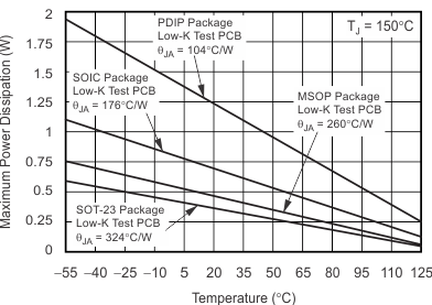
TLV2370 TLV2371 TLV2372 TLV2373 TLV2374 TLV2375 maximum_power_dissipation_vs_free_air_temp_slos270.gif
Results are with no air flow and using JEDEC Standard Low-K test PCB.
Figure 41. Maximum Power Dissipation vs Free-Air Temperature