ZHCSP76 November   2021 TMAG5124-Q1

PRODUCTION DATA  

  1.   1
  2. 特性
  3. 应用
  4. 说明
  5. Revision History
  6. Device Comparison
  7. Pin Configuration and Functions
  8. Specifications
    1. 7.1 Absolute Maximum Ratings
    2. 7.2 ESD Ratings
    3. 7.3 Recommended Operating Conditions
    4. 7.4 Thermal Information
    5. 7.5 Electrical Characteristics
    6. 7.6 Magnetic Characteristics
    7. 7.7 Typical Characteristics
      1. 7.7.1 TMAG5124A and TMAG5124E
      2. 7.7.2 TMAG5124B and TMAG5124F
      3. 7.7.3 TMAG5124C and TMAG5124G
      4. 7.7.4 TMAG5124D and TMAG5124H
      5. 7.7.5 Current Output Level
        1. 7.7.5.1 Low-Level Current Output for TMAG5124A/B/C/D
        2. 7.7.5.2 Low-Level Current Output for TMAG5124E/F/G/H
        3. 7.7.5.3 High-Level Current Output for Every Version
  9. Detailed Description
    1. 8.1 Overview
    2. 8.2 Functional Block Diagram
    3. 8.3 Feature Description
      1. 8.3.1 Field Direction Definition
      2. 8.3.2 Device Output
      3. 8.3.3 Protection Circuits
        1. 8.3.3.1 Load Dump Protection
        2. 8.3.3.2 Reverse Polarity Protection
      4. 8.3.4 Power-On Time
      5. 8.3.5 Hall Element Location
      6. 8.3.6 Propagation Delay
      7. 8.3.7 Chopper Stabilization
    4. 8.4 Device Functional Modes
  10. Application and Implementation
    1. 9.1 Application Information
    2. 9.2 Typical Applications
      1. 9.2.1 High-Side and Low-Side Typical Application Diagrams
        1. 9.2.1.1 Design Requirements
        2. 9.2.1.2 Detailed Design Procedure
        3. 9.2.1.3 Application Curve
  11. 10Power Supply Recommendations
    1. 10.1 Power Derating
  12. 11Layout
    1. 11.1 Layout Guidelines
    2. 11.2 Layout Example
  13. 12Device and Documentation Support
    1. 12.1 Documentation Support
    2. 12.2 接收文档更新通知
    3. 12.3 支持资源
    4. 12.4 Trademarks
    5. 12.5 静电放电警告
    6. 12.6 术语表
  14. 13Mechanical, Packaging, and Orderable Information

封装选项

机械数据 (封装 | 引脚)
散热焊盘机械数据 (封装 | 引脚)
订购信息

Device Output

When the device is powered on and no magnetic field is applied, the output stays at ICC(H). If the magnetic field increases above the BOP value, then the output turns to ICC(L). The output will remain at this value until the magnetic field decreases to a field value smaller than the BRP threshold.

The ICC(H) for all TMAG5124x versions is between 12 mA to 17 mA. The ICC(L) option for the TMAG5124D versions is ICC(L1), which is typically 3.5 mA, while The ICC(L) for the TMAG5124H versions is ICC(L2) and is typically 6 mA.
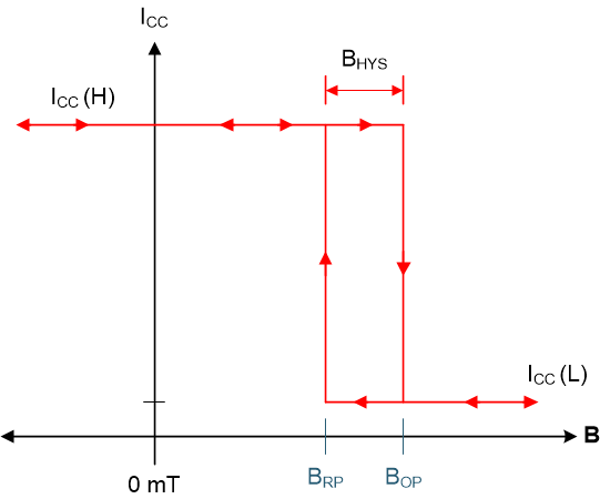
GUID-00E615D3-C973-4DBF-8DD4-90E65D44A5C3-low.gif Figure 8-3 Unipolar Functionality