ZHCSQO5C June 2024 – June 2024 TMAG5131-Q1
PRODUCTION DATA
- 1
- 1 特性
- 2 应用
- 3 说明
- 4 Device Comparison
- 5 Pin Configuration and Functions
- 6 Specifications
- 7 Detailed Description
- 8 Application and Implementation
- 9 Device and Documentation Support
- 10Revision History
- 11Mechanical and Packaging Information
8.1.1 Defining the Design Implementation
The first step of the design is identifying the general design implementation. Define whether the magnet that needs to be detected is sliding past the sensor, moving head-on toward the sensor, or swinging toward the sensor on a hinge. Figure 8-1 shows examples for each of the aforementioned design implementations.
 Figure 8-1 Design Implementations
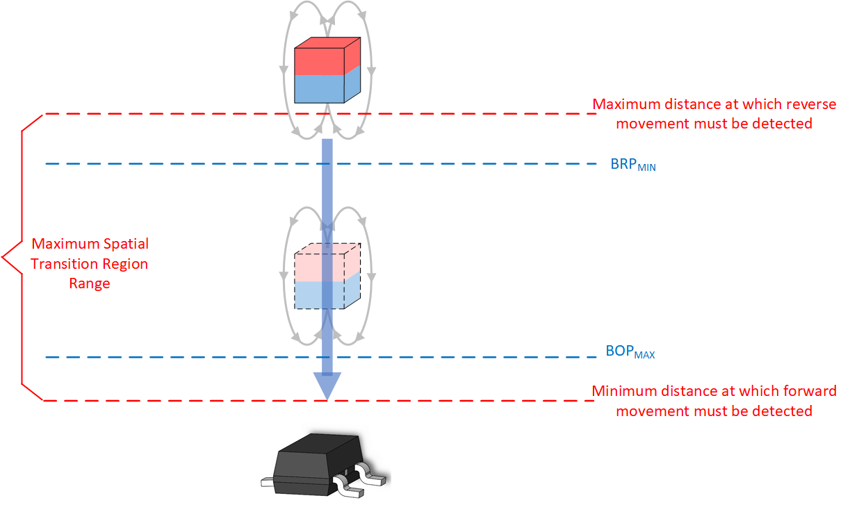
With each implementation, the objective is to design the system such that the spatial coordinates of the transition region fall within the spatial coordinates associated with the BOP maximum and BRP minimum specifications. Figure 8-2 shows a head-on example that shows how the location corresponding to the device BOPMAX and BRPMIN fall within the desired transition region. To facilitate rapid design iteration, TI’s Magnetic Sense Simulator (TIMSS) webtool is leveraged in the following design examples.
 Figure 8-2 Head-On
Example