SPRS377F September 2008 – June 2014 TMS320C6745 , TMS320C6747
PRODUCTION DATA.
- 1TMS320C6745, TMS320C6747 Fixed- and Floating-Point Digital Signal Processor
- 2Revision History
-
3Device Overview
- 3.1 Device Characteristics
- 3.2 Device Compatibility
- 3.3 DSP Subsystem
- 3.4 Memory Map Summary
- 3.5 Pin Assignments
- 3.6
Terminal Functions
- 3.6.1 Device Reset and JTAG
- 3.6.2 High-Frequency Oscillator and PLL
- 3.6.3 Real-Time Clock and 32-kHz Oscillator
- 3.6.4 External Memory Interface A (ASYNC, SDRAM)
- 3.6.5 External Memory Interface B (only SDRAM)
- 3.6.6 Serial Peripheral Interface Modules (SPI0, SPI1)
- 3.6.7 Enhanced Capture/Auxiliary PWM Modules (eCAP0, eCAP1, eCAP2)
- 3.6.8 Enhanced Pulse Width Modulators (eHRPWM0, eHRPWM1, eHRPWM2)
- 3.6.9 Enhanced Quadrature Encoder Pulse Module (eQEP)
- 3.6.10 Boot
- 3.6.11 Universal Asynchronous Receiver/Transmitters (UART0, UART1, UART2)
- 3.6.12 Inter-Integrated Circuit Modules (I2C0, I2C1)
- 3.6.13 Timers
- 3.6.14 Universal Host-Port Interface (UHPI)
- 3.6.15 Multichannel Audio Serial Ports (McASP0, McASP1, McASP2)
- 3.6.16 Universal Serial Bus Modules (USB0, USB1)
- 3.6.17 Ethernet Media Access Controller (EMAC)
- 3.6.18 Multimedia Card/Secure Digital (MMC/SD)
- 3.6.19 Liquid Crystal Display Controller (LCD)
- 3.6.20 General Purpose Input Output (GPIO)
- 3.6.21 Reserved and No Connect
- 3.6.22 Supply and Ground
- 3.6.23 Unused USB0 (USB2.0) and USB1 (USB1.1) Pin Configurations
- 4Device Configuration
-
5Device Operating Conditions
- 5.1 Absolute Maximum Ratings Over Operating Case Temperature Range (Unless Otherwise Noted)
- 5.2 Handling Ratings
- 5.3 Recommended Operating Conditions
- 5.4 Notes on Recommended Power-On Hours (POH)
- 5.5 Electrical Characteristics Over Recommended Ranges of Supply Voltage and Operating Case Temperature (Unless Otherwise Noted)
-
6Peripheral Information and Electrical Specifications
- 6.1 Parameter Information
- 6.2 Recommended Clock and Control Signal Transition Behavior
- 6.3 Power Supplies
- 6.4 Reset
- 6.5 Crystal Oscillator or External Clock Input
- 6.6 Clock PLLs
- 6.7 Interrupts
- 6.8 General-Purpose Input/Output (GPIO)
- 6.9 EDMA
- 6.10 External Memory Interface A (EMIFA)
- 6.11 External Memory Interface B (EMIFB)
- 6.12 Memory Protection Units
- 6.13 MMC / SD / SDIO (MMCSD)
- 6.14 Ethernet Media Access Controller (EMAC)
- 6.15 Management Data Input/Output (MDIO)
- 6.16 Multichannel Audio Serial Ports (McASP0, McASP1, and McASP2)
- 6.17
Serial Peripheral Interface Ports (SPI0, SPI1)
- 6.17.1 SPI Peripheral Registers Description(s)
- 6.17.2
SPI Electrical Data/Timing
- 6.17.2.1
Serial Peripheral Interface (SPI) Timing
- Table 6-54 General Timing Requirements for SPI0 Master Modes
- Table 6-55 General Timing Requirements for SPI0 Slave Modes
- Table 6-56 Additional SPI0 Master Timings, 4-Pin Enable Option
- Table 6-57 Additional SPI0 Master Timings, 4-Pin Chip Select Option
- Table 6-58 Additional SPI0 Master Timings, 5-Pin Option
- Table 6-59 Additional SPI0 Slave Timings, 4-Pin Enable Option
- Table 6-60 Additional SPI0 Slave Timings, 4-Pin Chip Select Option
- Table 6-61 Additional SPI0 Slave Timings, 5-Pin Option
- Table 6-62 General Timing Requirements for SPI1 Master Modes
- Table 6-63 General Timing Requirements for SPI1 Slave Modes
- Table 6-64 Additional SPI1 Master Timings, 4-Pin Enable Option
- Table 6-65 Additional SPI1 Master Timings, 4-Pin Chip Select Option
- Table 6-66 Additional SPI1 Master Timings, 5-Pin Option
- Table 6-67 Additional SPI1 Slave Timings, 4-Pin Enable Option
- Table 6-68 Additional SPI1 Slave Timings, 4-Pin Chip Select Option
- Table 6-69 Additional SPI1 Slave Timings, 5-Pin Option
- 6.17.2.1
Serial Peripheral Interface (SPI) Timing
- 6.18 Enhanced Capture (eCAP) Peripheral
- 6.19 Enhanced Quadrature Encoder (eQEP) Peripheral
- 6.20 Enhanced High-Resolution Pulse-Width Modulator (eHRPWM)
- 6.21 LCD Controller
- 6.22 Timers
- 6.23 Inter-Integrated Circuit Serial Ports (I2C0, I2C1)
- 6.24 Universal Asynchronous Receiver/Transmitter (UART)
- 6.25 USB1 Host Controller Registers (USB1.1 OHCI)
- 6.26 USB0 OTG (USB2.0 OTG)
- 6.27 Host-Port Interface (UHPI)
- 6.28 Power and Sleep Controller (PSC)
- 6.29 Programmable Real-Time Unit Subsystem (PRUSS)
- 6.30 Emulation Logic
- 6.31 IEEE 1149.1 JTAG
- 6.32 Real Time Clock (RTC)
- 7Device and Documentation Support
- 8Mechanical Packaging and Orderable Information
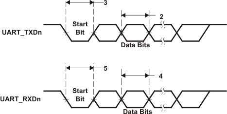
Table 6-93 Switching Characteristics Over Recommended Operating Conditions for UARTx Transmit(1)
(see Figure 6-65)
| No. | PARAMETER | MIN | MAX | UNIT | |
|---|---|---|---|---|---|
| 1 | f(baud) | Maximum programmable baud rate | D/E (2)(3) | MBaud(4) | |
| 2 | tw(UTXDB) | Pulse duration, transmit data bit (TXDn) | U - 2 | U + 2 | ns |
| 3 | tw(UTXSB) | Pulse duration, transmit start bit | U - 2 | U + 2 | ns |
(1) U = UART baud time = 1/programmed baud rate.
(2) D = UART input clock in MHz. The UART(s) input clock source is PLL0_SYSCLK2.
(3) E = UART divisor x UART sampling rate. The UART divisor is set through the UART divisor latch registers (DLL and DLH). The UART sampling rate is set through the over-sampling mode select bit (OSM_SEL) of the UART mode definition register (MDR).
(4) Baud rate is not indicative of data rate. Actual data rate will be limited by system factors such as EDMA loading, EMIF loading, system frequency, etc.
 Figure 6-65 UART Transmit/Receive Timing