ZHCSAL0D March 2016 – August 2020 TPD3S716-Q1
PRODUCTION DATA
- 1 特性
- 2 应用
- 3 说明
- 4 Revision History
- 5 Pin Configuration and Functions
- 6 Specifications
- 7 Parameter Measurement Information
-
8 Detailed Description
- 8.1 Overview
- 8.2 Functional Block Diagram
- 8.3
Feature Description
- 8.3.1 AEC-Q100 Qualified
- 8.3.2 Short-to-Battery and Short-to-Ground Protection on VBUS_CON
- 8.3.3 Short-to-Battery and Short-to-VBUS Protection on VD+, VD–
- 8.3.4 ESD Protection on VBUS_CON, VD+, VD–
- 8.3.5 Low RON nFET VBUS Switch
- 8.3.6 High Speed Data Switches
- 8.3.7 Adjustable Hiccup Current Limit up to 2.4-A
- 8.3.8 Fast Over-Voltage Response Time
- 8.3.9 Independent VBUS and Data Enable Pins for Configuring both Host and Client/OTG Mode
- 8.3.10 Fault Output Signal
- 8.3.11 Thermal Shutdown Feature
- 8.3.12 16-Pin SSOP Package
- 8.3.13 Reverse Current Detection
- 8.4 Device Functional Modes
- 9 Application and Implementation
- 10Power Supply Recommendations
- 11Layout
- 12Device and Documentation Support
- 13Mechanical, Packaging, and Orderable Information
8.3.7 Adjustable Hiccup Current Limit up to 2.4-A
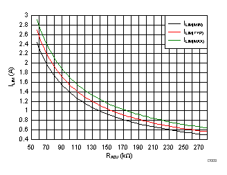
The VBUS path of this device has an integrated overcurrent protection circuit. The current limit threshold for the overcurrent protection is adjustable via an external resistor RADJ to GND on the IADJ pin. Equation 1 to Equation 3 approximate the minimum, nominal, and maximum current limit values for TPD3S716-Q1 assuming a 1% tolerant resistor:
where
- ILIM(TYP) is the nominal current limit value in (A)
- ILIM(MIN) is the minimum current limit value in (A)
- ILIM(MAX) is the maximum current limit value in (A)
- RADJ is the nominal resistor to GND on the IADJ pin in (Ω)
 Figure 8-1 TPD3S716-Q1 Current Limit Thresholds vs. RADJ
Equation 1, Equation 2 and Equation 3 are useful for approximating the current limit threshold of TPD3S716-Q1; however, they do not constitute as part of TI's published device specifications for purposes of TI's product warranty. For the officially tested current limit threshold values, see the Electrical Characteristics table.
When the VBUS current exceeds the overcurrent threshold, the device goes into a fault state where it limits the current to the overcurrent threshold value and asserts the FLT pin. After a short blanking time, the device cycles on and off to try to check if the connected device is still in overcurrent.