ZHCSAP5E December   2012  – October 2024 TPD4E1B06

PRODUCTION DATA  

  1.   1
  2. 特性
  3. 应用
  4. 说明
  5. Pin Configuration and Functions
  6. Specifications
    1. 5.1 Absolute Maximum Ratings
    2. 5.2 ESD Ratings
    3. 5.3 Recommended Operating Conditions
    4. 5.4 Thermal Information
    5. 5.5 Electrical Characteristics
    6. 5.6 Typical Characteristics
  7. Detailed Description
    1. 6.1 Overview
    2. 6.2 Functional Block Diagram
    3. 6.3 Feature Description
      1. 6.3.1 Ultra Low Leakage Current 0.5 nA (Maximum)
      2. 6.3.2 Transient Protection for 4 I/O Lines
      3. 6.3.3 I/O Capacitance 0.7 pF (Typical)
      4. 6.3.4 Bi-Directional (ESD) Protection Diode Array
      5. 6.3.5 Low ESD Clamping Voltage
    4. 6.4 Device Functional Modes
  8. Application and Implementation
    1. 7.1 Application Information
    2. 7.2 Typical Application
      1. 7.2.1 Design Requirements
      2. 7.2.2 Detailed Design Procedure
        1. 7.2.2.1 Signal Range on IO1, IO2, IO3, and IO4 Pins
        2. 7.2.2.2 Operating Frequency
      3. 7.2.3 Application Curves
    3. 7.3 Layout
      1. 7.3.1 Layout Guidelines
      2. 7.3.2 Layout Examples
  9. Device and Documentation Support
    1. 8.1 接收文档更新通知
    2. 8.2 支持资源
    3. 8.3 Trademarks
    4. 8.4 静电放电警告
    5. 8.5 术语表
  10. Revision History
  11. 10Mechanical, Packaging, and Orderable Information

封装选项

机械数据 (封装 | 引脚)
散热焊盘机械数据 (封装 | 引脚)
订购信息

Typical Characteristics

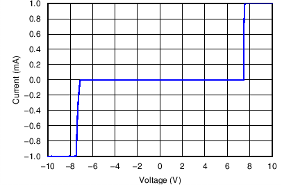
TPD4E1B06 DC Voltage Sweep I-V CurveFigure 5-1 DC Voltage Sweep I-V Curve
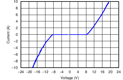
TPD4E1B06 TLP Plot IO to GNDFigure 5-3 TLP Plot IO to GND
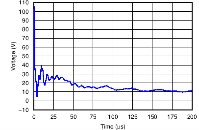
TPD4E1B06 +8 kV IEC WaveformFigure 5-5 +8 kV IEC Waveform
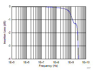
TPD4E1B06 Insertion LossFigure 5-7 Insertion Loss
TPD4E1B06 Surge Curve (tp = 8/20 μs), Pin IO to GNDFigure 5-2 Surge Curve (tp = 8/20 μs), Pin IO to GND
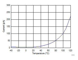
TPD4E1B06 Leakage vs TemperatureFigure 5-4 Leakage vs Temperature
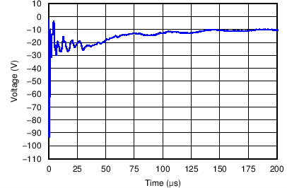
TPD4E1B06 –8 kV IEC WaveformFigure 5-6 –8 kV IEC Waveform
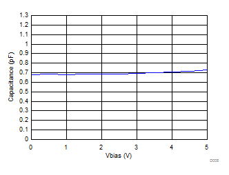
TPD4E1B06 Capacitance vs VBIASFigure 5-8 Capacitance vs VBIAS