SLLSE38B June 2010 – March 2016 TPD8E003
PRODUCTION DATA.
- 1 Features
- 2 Applications
- 3 Description
- 4 Revision History
- 5 Pin Configuration and Functions
- 6 Specifications
- 7 Detailed Description
- 8 Application and Implementation
- 9 Power Supply Recommendations
- 10Layout
- 11Device and Documentation Support
- 12Mechanical, Packaging, and Orderable Information
7 Detailed Description
7.1 Overview
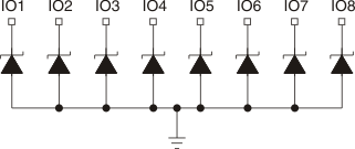
The TPD8E003 is a unidirectional TVS-based, ESD protection diode array. The TPD8E003 is rated to dissipate ESD strikes above the maximum level specified in the IEC 61000-4-2 international standard (Level 4). This device provides 8 channels of ESD protection in a space-saving WSON package.
7.2 Functional Block Diagram

7.3 Feature Description
7.3.1 IEC 61000-4-2 ESD Protection
The I/O pins can withstand ESD events up to ±12-kV contact and ±15-kV air gap. An ESD/surge clamp diverts the current to ground.
7.3.2 IEC 61000-4-5 Surge Protection
The I/O pins can withstand surge events up to 3.5 A and 55 W (8/20 µs waveform). An ESD/surge clamp diverts this current to ground.
7.3.3 IO Capacitance
The capacitance between each I/O pin-to-ground is 9 pF (typical) and 12 pF (maximum).
7.3.4 DC Breakdown Voltage
The DC breakdown voltage of each I/O pin is a minimum of 6 V. This ensures that sensitive equipment is protected from surges above the reverse standoff voltage of 5.5 V.
7.3.5 Low Leakage Current
The I/O pins feature an low leakage current of 100 nA (maximum) with a bias of 2.5 V.
7.3.6 Industrial Temperature Range
This device features an industrial operating range of –40°C to 85°C.
7.3.7 Space-Saving Package
This device features a space-saving WSON package that puts many channels of ESD in a small form factor.
7.4 Device Functional Modes
TPD8E003 is a passive integrated circuit that triggers when voltages are above VBR or below the lower diodes Vf (–0.6 V). During ESD events, voltages as high as ±15 kV (air) can be directed to ground through the internal diode network. When the voltages on the protected line fall below the trigger levels of TPD8E003 (usually within 10s of nano-seconds) the device reverts to passive.