ZHCSSK0P April   2004  – August 2024 TPS2041B , TPS2042B , TPS2043B , TPS2044B , TPS2051B , TPS2052B , TPS2053B , TPS2054B

PRODUCTION DATA  

  1.   1
  2. 特性
  3. 应用
  4. 说明
  5. General Switch Catalog
  6. Pin Configuration and Functions
  7. Specifications
    1. 6.1 Absolute Maximum Ratings
    2. 6.2 ESD Ratings
    3. 6.3 Recommended Operating Conditions
    4. 6.4 Thermal Information
    5. 6.5 Electrical Characteristics
    6. 6.6 Typical Characteristics (All Devices Excluding TPS2051BDBV and TPS2052BD)
    7. 6.7 Typical Characteristics (TPS2051BDBV and TPS2052BD)
  8. Parameter Measurement Information
  9. Detailed Description
    1. 8.1 Overview
    2. 8.2 Functional Block Diagrams
    3. 8.3 Feature Description
      1. 8.3.1  Power Switch
      2. 8.3.2  Charge Pump
      3. 8.3.3  Driver
      4. 8.3.4  Enable ( ENx)
      5. 8.3.5  Enable (ENx)
      6. 8.3.6  Current Sense
      7. 8.3.7  Overcurrent
        1. 8.3.7.1 Overcurrent Conditions (TPS20x3BD, TPS20x4BD, and TPS20x2BDRB)
        2. 8.3.7.2 Overcurrent Conditions (TPS20x1B & TPS20x2B in D, DGN, and DBV packages)
      8. 8.3.8  Overcurrent ( OCx)
      9. 8.3.9  Thermal Sense
      10. 8.3.10 Undervoltage Lockout
    4. 8.4 Device Functional Modes
  10. Application and Implementation
    1. 9.1 Application Information
      1. 9.1.1 Universal Serial Bus (USB) Applications
    2. 9.2 Typical Application
      1. 9.2.1 Typical Application (TPS2042B)
        1. 9.2.1.1 Design Requirements
        2. 9.2.1.2 Detailed Design Procedure
          1. 9.2.1.2.1 Power-Supply Considerations
          2. 9.2.1.2.2 OC Response
        3. 9.2.1.3 Application Curves
      2. 9.2.2 Host and Self-Powered and Bus-Powered Hubs
        1. 9.2.2.1 Design Requirements
          1. 9.2.2.1.1 USB Power-Distribution Requirements
        2. 9.2.2.2 Detailed Design Procedure
          1. 9.2.2.2.1 Low-Power Bus-Powered and High-Power Bus-Powered Functions
        3. 9.2.2.3 Application Curves
      3. 9.2.3 Generic Hot-Plug Applications
        1. 9.2.3.1 Design Requirements
        2. 9.2.3.2 Detailed Design Procedure
        3. 9.2.3.3 Application Curves
  11. 10Power Supply Recommendations
    1. 10.1 Undervoltage Lockout (UVLO)
  12. 11Layout
    1. 11.1 Layout Guidelines
    2. 11.2 Layout Example
    3. 11.3 Power Dissipation
    4. 11.4 Thermal Protection
  13. 12Device and Documentation Support
    1. 12.1 接收文档更新通知
    2. 12.2 支持资源
    3. 12.3 Trademarks
    4. 12.4 静电放电警告
    5. 12.5 术语表
  14. 13Revision History
  15. 14Mechanical, Packaging, and Orderable Information

封装选项

机械数据 (封装 | 引脚)
散热焊盘机械数据 (封装 | 引脚)
订购信息

说明

TPS20xxB 配电开关适用于可能具有高容性负载和发生短路的应用。此系列器件包含 70mΩ N 沟道 MOSFET 电源开关,适用于需要在单个封装内包含多个电源开关的配电系统。每个开关由一个逻辑使能输入控制。栅极驱动由一个内部电荷泵提供,此电荷泵设计用于控制电源开关上升时间和下降时间以大大减少切换期间的电流涌入。电荷泵无需外部组件并可在低至 2.7V 的电源电压下工作。

当输出负载超过限流阈值或者短路出现时,该器件通过切换至恒定电流模式,并通过将过流 (OCx) 下拉至逻辑输出低电平来将输出电流限制在安全水平上。如果持续重过载和短路增加了开关内的功率耗散,则将引起结温上升,此时,过热保护电路将关闭此开关以避免器件损坏。一旦器件充分冷却,此器件将自动从热关断中恢复。内部电路确保此开关在有效输入电压出现前保持关闭状态。此配电开关旨在将电流限制设置为 1A(典型值)。

器件信息
器件型号封装(1)本体尺寸(标称值)
TPS20xxBSOIC (8)4.90mm × 3.91mm
SOIC (16)9.90mm × 3.91mm
SOT-23 (5)2.90mm × 1.60mm
HVSSOP (8)3.00mm × 3.00mm
SON (8)3.00mm × 3.00mm
如需了解所有可用封装,请参阅数据表末尾的可订购米6体育平台手机版_好二三四附录。
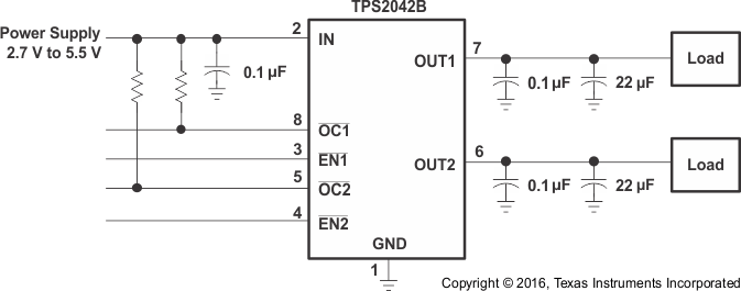
TPS2041B TPS2042B TPS2043B TPS2044B  TPS2051B TPS2052B TPS2053B TPS2054B 典型应用原理图典型应用原理图