ZHCSIQ0F August   2018  – August 2020 TPS2120 , TPS2121

PRODUCTION DATA  

  1. 特性
  2. 应用
  3. 说明
  4. Revision History
  5. Device Comparison Table
  6. Pin Configuration and Functions
    1.     7
  7. Specifications
    1. 7.1 Absolute Maximum Ratings
    2. 7.2 ESD Ratings
    3. 7.3 Recommended Operating Conditions
    4. 7.4 Thermal Information
    5. 7.5 Electrical Characteristics
    6. 7.6 Typical Characteristics
  8. Parameter Measurement Information
  9. Detailed Description
    1. 9.1 Overview
    2. 9.2 Functional Block Diagram
    3. 9.3 Feature Description
      1. 9.3.1 Input Settling Time and Output Soft Start Control (SS)
        1. 9.3.1.1 Slew Rate vs. CSS Capacitor
      2. 9.3.2 Active Current Limiting (ILM)
      3. 9.3.3 Short-Circuit Protection
      4. 9.3.4 Thermal Protection (TSD)
      5. 9.3.5 Overvoltage Protection (OVx)
      6. 9.3.6 Fast Reverse Current Blocking (RCB)
      7. 9.3.7 Output Voltage Dip and Fast Switchover Control (TPS2121 only)
      8. 9.3.8 Input Voltage Comparator (VCOMP)
    4. 9.4 TPS2120 Device Functional Modes
    5. 9.5 TPS2121 Device Functional Modes
  10. 10Application and Implementation
    1. 10.1 Application Information
    2. 10.2 Typical Application
      1. 10.2.1 Manual Switchover Schematic
      2. 10.2.2 Design Requirements
      3. 10.2.3 Detailed Design Description
      4. 10.2.4 Design Procedure
        1. 10.2.4.1 Selecting PR1 and CP2 Resistors
        2. 10.2.4.2 Selecting OVx Resistors
        3. 10.2.4.3 Selecting Soft-Start Capacitor and Current Limit Resistors
      5. 10.2.5 Application Curves
    3. 10.3 Automatic Switchover with Priority (XCOMP)
      1. 10.3.1 Application Schematic
      2. 10.3.2 Design Requirements
      3. 10.3.3 Detailed Design Description
      4. 10.3.4 Design Procedure
        1. 10.3.4.1 Selecting PR1 and CP2 Resistors
      5. 10.3.5 Application Curves
    4. 10.4 Automatic Seamless Switchover with Priority (XREF)
      1. 10.4.1 Application Schematic
      2. 10.4.2 Design Requirements
      3. 10.4.3 Detailed Design Description
      4. 10.4.4 Application Curves
    5. 10.5 Highest Voltage Operation (VCOMP)
      1. 10.5.1 Application Schematic
      2. 10.5.2 Design Requirements
      3. 10.5.3 Detailed Design Description
      4. 10.5.4 Detailed Design Procedure
      5. 10.5.5 Application Curves
    6. 10.6 Reverse Polarity Protection with TPS212x
    7. 10.7 Hotplugging with TPS212x
  11. 11Power Supply Recommendations
  12. 12Layout
    1. 12.1 Layout Guidelines
    2. 12.2 Layout Example
  13. 13Device and Documentation Support
    1. 13.1 Documentation Support
      1. 13.1.1 Related Links
    2. 13.2 接收文档更新通知
    3. 13.3 支持资源
    4. 13.4 Trademarks
    5. 13.5 静电放电警告
    6. 13.6 术语表
  14. 14Mechanical, Packaging, and Orderable Information

封装选项

请参考 PDF 数据表获取器件具体的封装图。

机械数据 (封装 | 引脚)
  • RUX|12
散热焊盘机械数据 (封装 | 引脚)
订购信息

说明

TPS212x 器件是双输入、单输出 (DISO) 电源多路复用器 (MUX),非常适合用于各种多电源系统。这些器件能够在可用输入之间自动检测、选择和无缝转换。

 优先级可自动分配给最高输入电压或手动分配给较低的电压输入,以支持 ORing 和资源选择操作。优先级电压监控器用于选择输入源。

 理想二极管运行用于在输入源之间无缝转换。在切换期间,需对压降进行控制以阻止反向电流的发生,并以最小的保持电容为负载提供不间断电源。

在启动和切换期间,需对电流进行限制以防止过流事件,同时在器件正常工作期间为其提供保护。可使用单个外部电阻器调节输出电流限制。

 TPS212x 器件采用 WCSP 和小型 VQFN-HR 封装选项,可在 -40°C 至 125°C 的温度范围内正常运行。

器件信息
器件型号 封装(1) 封装尺寸(标称值)
TPS2120 WCSP (20) 1.5mm x 2.0mm
TPS2121 VQFN-HR (12) 2.0mm x 2.5mm
要了解所有可用封装,请见数据表末尾的可订购米6体育平台手机版_好二三四附录。
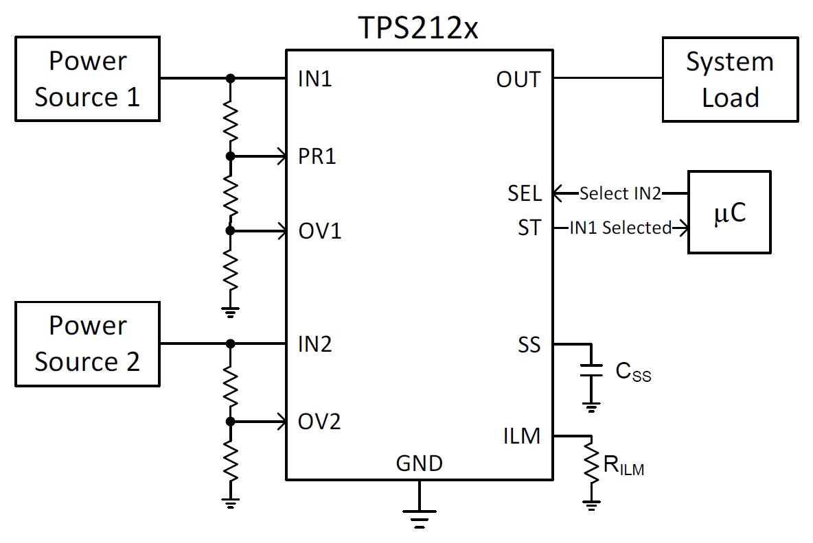
GUID-F7AD808F-A073-412E-8370-6550FC6A4036-low.jpg典型应用