SLVS984B September 2009 – March 2015 TPS22946
PRODUCTION DATA.
- 1 Features
- 2 Applications
- 3 Description
- 4 Revision History
- 5 Pin Configuration and Functions
- 6 Specifications
- 7 Parameter Measurement Information
- 8 Detailed Description
- 9 Application and Implementation
- 10Power Supply Recommendations
- 11Layout
- 12Device and Documentation Support
- 13Mechanical, Packaging, and Orderable Information
8 Detailed Description
8.1 Overview
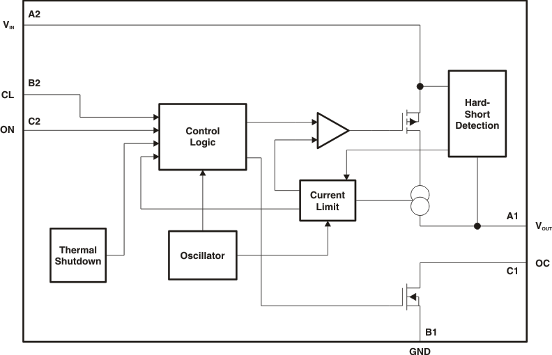
The TPS22946 is an ultralow power load switch that provides protection to systems and loads in high-current conditions. The device contains a 300-mΩ current-limited P-channel MOSFET that can operate over an input voltage range of 1.62 V to 5.5 V. The switch is controlled by an on/off input (ON), which is capable of interfacing directly with low-voltage control signals. The TPS22946 includes thermal shutdown protection that prevents damage to the device when a continuous over-current condition causes excessive heating by turning off the switch.
When the switch current reaches the maximum limit, the TPS22946 operates in a constant-current mode to prohibit excessive currents from causing damage. The current limit can be selected using the CL input: a high CL input sets the current limit to 155 mA, a low CL input sets the current limit to 70 mA, and a floating CL input sets the current limit to 30 mA.
If the constant current condition still persists after 10 ms, the switch is turned off and the fault signal pin (OC) is pulled low. The TPS22946 has an auto-restart feature which turns the switch on again after 70 ms if the ON pin is still active. If the TPS22946 remains in an over-current condition for 5 seconds, the device shuts off until it is turned on again by setting the ON control signal off and then on.
If the device is used to protect an LDO, the inrush current required by the LDO at startup can, in some cases, exceed the current limit and initiate a blanking (current limiting) condition. The TPS22946 device provides allowance for this scenario during startup of the LDO by temporarily increasing the current limit to 435 mA for 8 ms after the load switch is enabled.
The TPS22946 is available in a space-saving 6-pin DSBGA (YZP) package. The device is characterized for operation over the free-air temperature range of –40°C to 85°C.
Table 1. Feature List
| rON (TYP) AT 5.5 V | CURRENT LIMIT | INTEGRATED INRUSH CURRENT TIME-OUT | CURRENT LIMIT BLANKING TIME | AUTO- RESTART TIME | OVERCURRENT TIME-OUT | ENABLE | |
|---|---|---|---|---|---|---|---|
| TPS22946 | 300 mΩ | 30 mA, 70 mA, or 155 mA | Yes | 10 ms | 70 ms | 6 s | Active high |
8.2 Functional Block Diagram
8.3 Feature Description
8.3.1 Detection Schemes
8.3.1.1 Overtemperature Detection
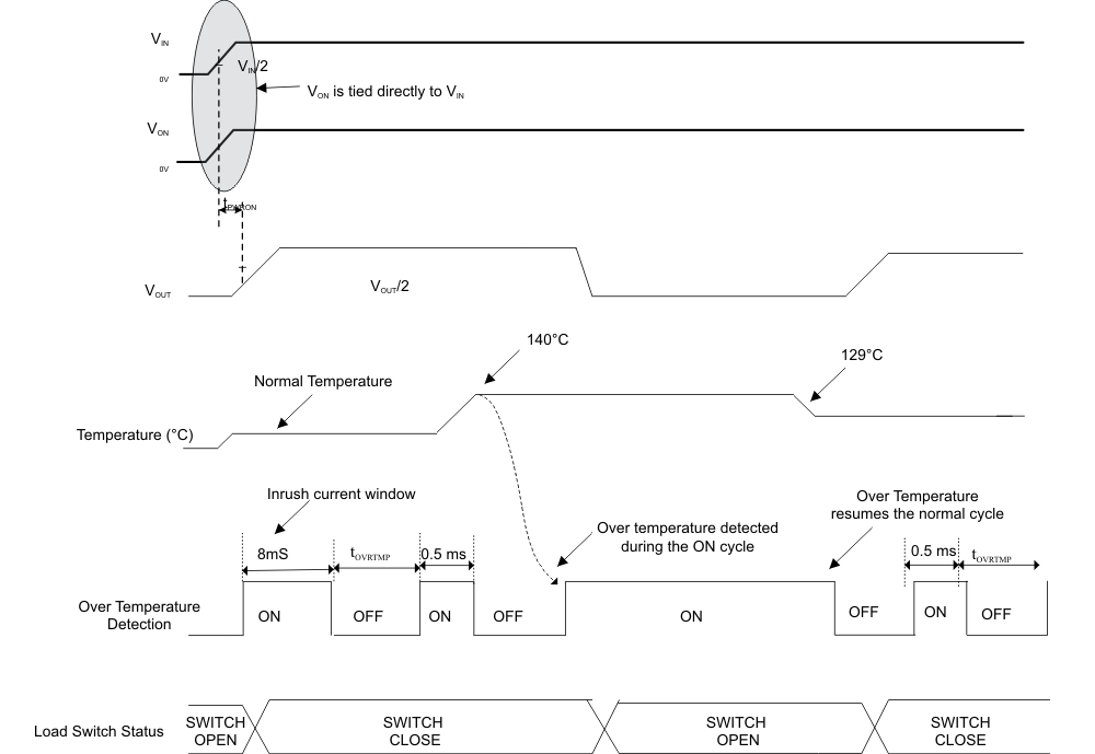
The thermal shutdown detection circuit is active every 8 ms for a period of 0.5 ms. The thermal shutdown protects the part from internally or externally generated excessive temperatures. During an over-temperature condition the switch is turned-off (Open). The switch automatically turns-on (closes) again if temperature of the die drops below the threshold temperature while the part is still enabled.
In addition, if an overcurrent fault condition is detected due to a moderate overcurrent or a hard-short, the thermal shutdown is activated immediately and stays on continuously for the duration of blanking (see Figure 32).
NOTE:
Case where the temperature causes the overtemperature detection circuit to trip before the other detection schemes.8.3.1.2 Hard-Short Detection
The hard-short detection circuit is active every 250 μs for a period of 125 μs. A comparator monitors the output voltage, VOUT. A hard short is detected when VOUT is lower than 2/3 VIN. The switch then goes into current-limiting mode.
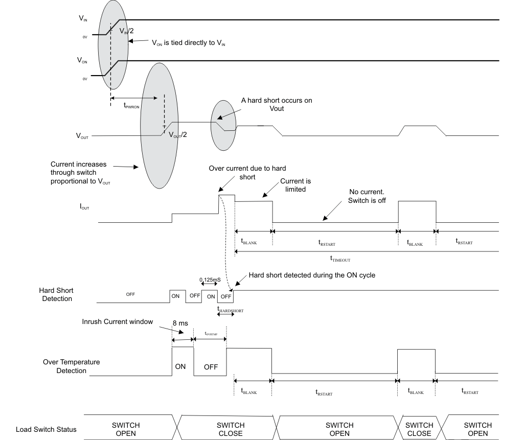 Figure 23. Hard-Short Detection
8.3.1.3 Moderate Overcurrent Detection
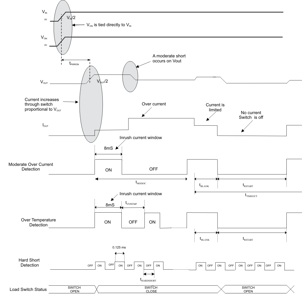
The moderate overcurrent detection circuit is active every 64 ms for a period of 0.5 ms. A moderate over-current condition is triggered when the output current of the switch exceeds the current limit value and is not yet into hard short condition. The switch then goes into current-limiting mode.
NOTE:
The overcurrent does not cause the temperature to go above 140°C here.8.3.1.4 Current Limiting Mode
When an overcurrent condition (moderate or a hard short) is detected, the TPS22946 operates in a constant-current mode to prohibit excessive currents from causing damage. TPS22946 has a current limit of 30 mA, 70 mA, or 155 mA.
If the constant current condition still persists after 10ms, the device shuts off the switch and pulls the fault signal pin (OC) low. The TPS22946 has an auto-restart feature which turns the switch on again after 70 ms if the ON pin is still active.
8.3.1.5 Fault Reporting
When a moderate overcurrent, hard short or overtemperature condition is detected, OC is set active low to signal a fault condition. OC is an open-drain MOSFET and requires a pullup resistor between VIN and OC. During shutdown, the pulldown on OC is disabled, reducing current draw from the supply.
8.3.1.6 Power-On and Power-Off Sequence
The device is enabled internally only once the hard-short detection circuit is enabled.
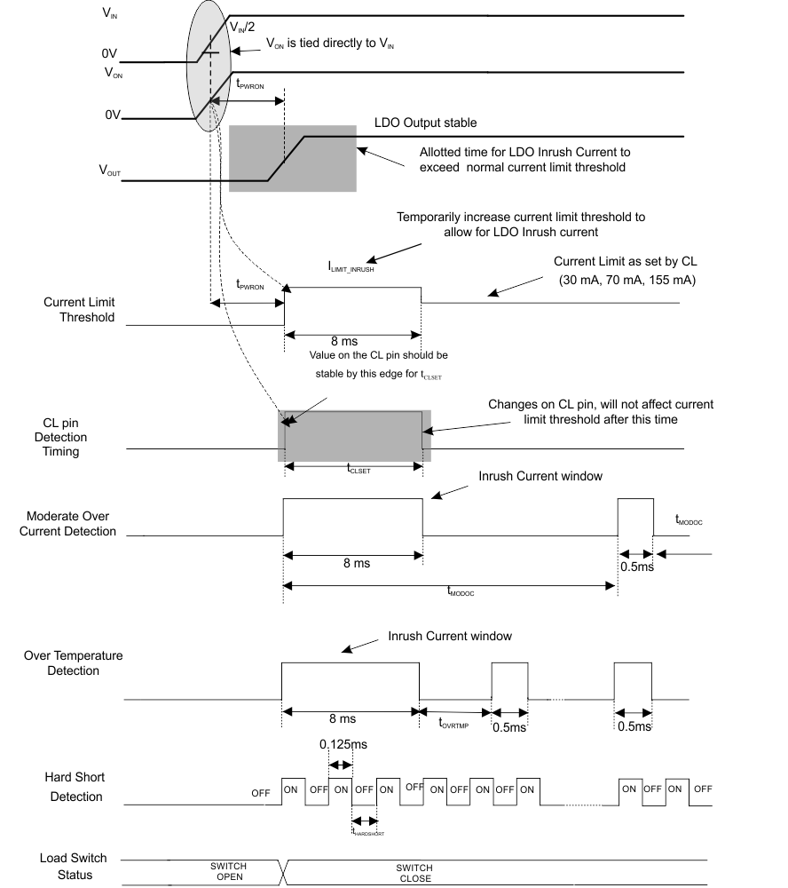 Figure 25. Power-On/Power-Off Sequence Timing
8.3.1.7 Automatic Disable in Case of Permanent Overcurrent
When the switch enters the current-limiting mode due to a hard short condition or a moderate over-current condition, TPS22946 goes through the 10-ms blanking state and the 70-ms auto restart state. If the hard-short condition or the moderate over-current condition persists after 5 s, the part shuts off regardless of the ON signal. The switch is turned on again after a power reset if the ON pin is HIGH.
8.3.2 Inrush Current Time-out Feature
The inrush current required by the LDO at startup can in some cases exceed the current limit and initiate a blanking (current limiting) condition. TPS22946 provides allowance for this scenario by temporarily increasing the current limit to 435 mA for 8 ms after the load switch is enabled. This time-out is initiated by the positive edge transition on the ON signal.
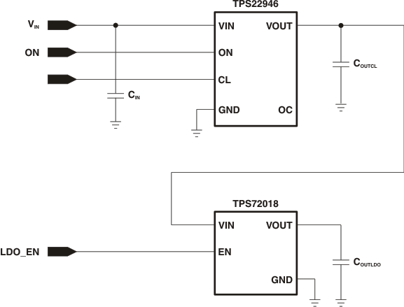 Figure 26. Inrush Current Time-out Circuit
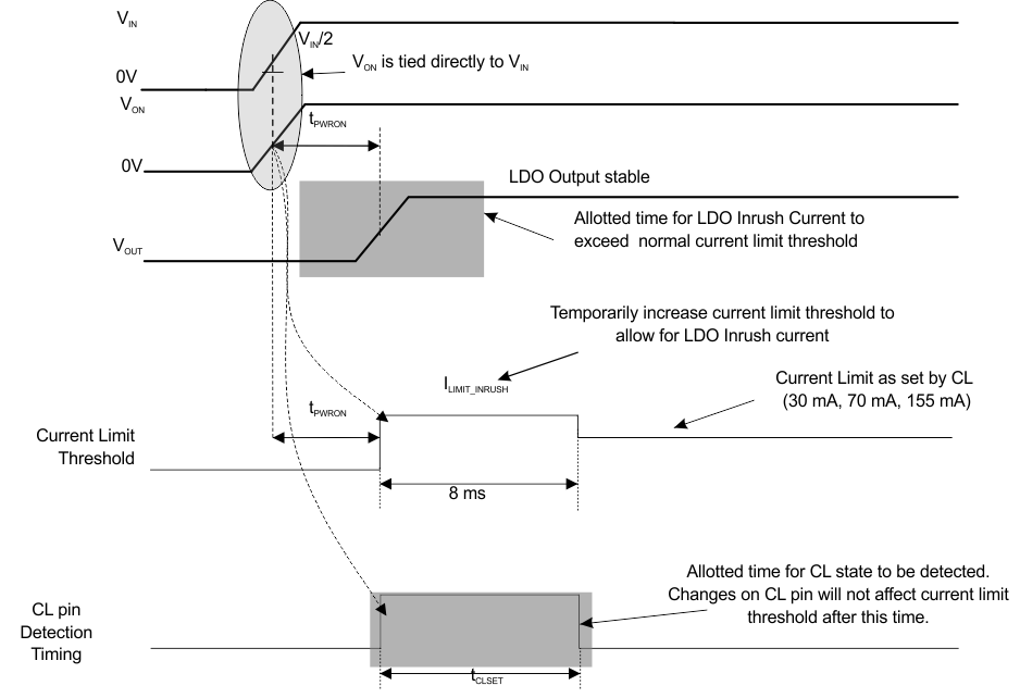 Figure 27. Inrush Current Time-out Timing
8.3.3 CL Control Pin
The TPS22946 supports three current limits: 30 mA, 70 mA, and 155 mA. The current limit selection is determined by the status of the digital input CL pin, as shown in Table 2. A high impedance, or floating, condition allows the CL pin to support a third state. The TPS22946 monitors the state of the CL pin during start-up from a disabled state, and upon start-up sets the current limit accordingly. When floating the CL pin, keep the total capacitance on the pin less than 100 pF and the resistive loading greater than 10 MΩ to ensure proper operation. Any changes to the state of the CL pin after the start-up operation has completed are ignored until the next start-up cycle.
The CL pin must be driven with logic levels referenced to VIN. The CL pin can be tied high or low on the printed wiring board (PWB) or driven by a general purpose I/O (GPIO), as long as the VIL and VIH recommended operating conditions are met.
Table 2. CL Control Pin
| CL PIN STATUS | CURRENT LIMIT |
|---|---|
| Logic low(2) | 70 mA |
| Float(1) | 30 mA |
| Logic high(2) | 155 mA |
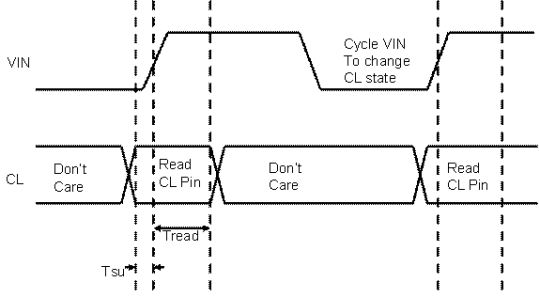 Figure 28. CL Pin Read Timing When cycling VIN (ON Pin Tied to VIN)
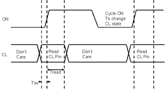 Figure 29. CL Pin Read Timing Cycling ON Pin (VIN High)
8.3.4 Overtemperature Protection
An overtemperature condition occurs when the temperature of the part is greater than 140°C. The OC flag will go low to indicate a fault. If the overtemperature condition persists for more than 6 seconds, the part times out and shuts OFF. The part must be enabled by either toggling the ON pin or the VIN pin. If the temperature falls below 130°C within 5 seconds, the part will start normal operation.
If the temperature is not constantly high above 140°C and is toggling between greater than 140°C and less than 130°C, the internal time-out timer keeps resetting. If this event occurs more than 32 times, it will cause the part to shut OFF. It can be enabled by toggling either the ON pin or the VIN pin.
8.4 Device Functional Modes
Table 3. Function Table
| ON | CL | TPS22946 |
|---|---|---|
| L | x | VIN to VOUT switch is off (open) |
| H | x | VIN to VOUT switch is on (closed) |
| x | H(2) | Current limit set to 155 mA |
| x | L(2) | Current limit set to 70 mA |
| x | Float(1) | Current limit set to 30 mA |
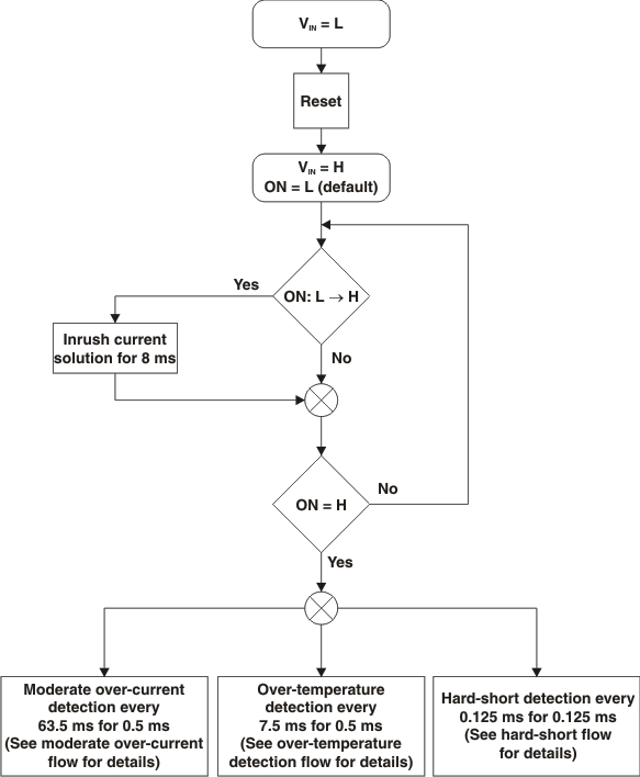 Figure 30. Functional Flow Diagram
 Figure 31. Moderate Overcurrent Detection Flow Diagram
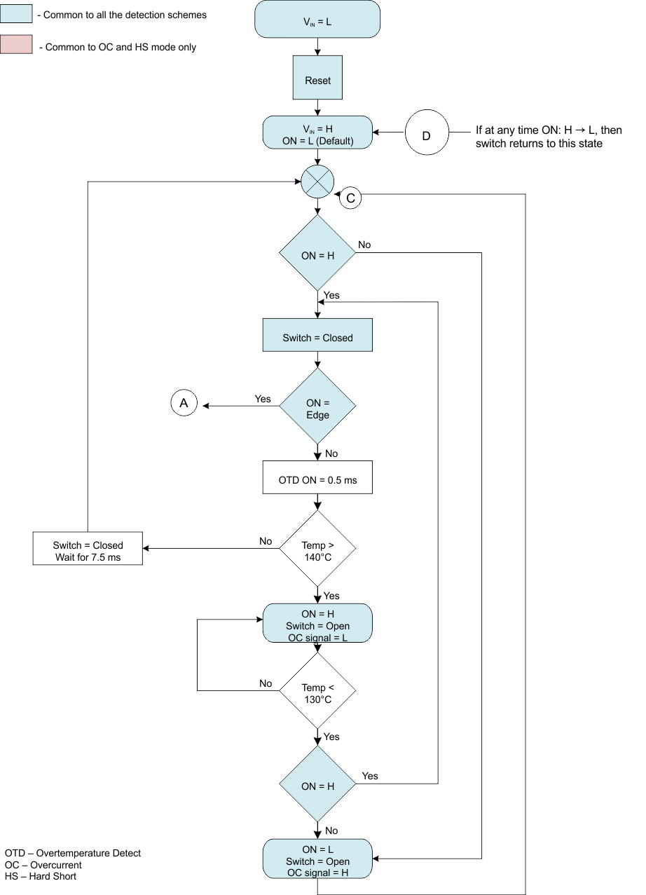 Figure 32. Overtemperature Detection Flow Diagram
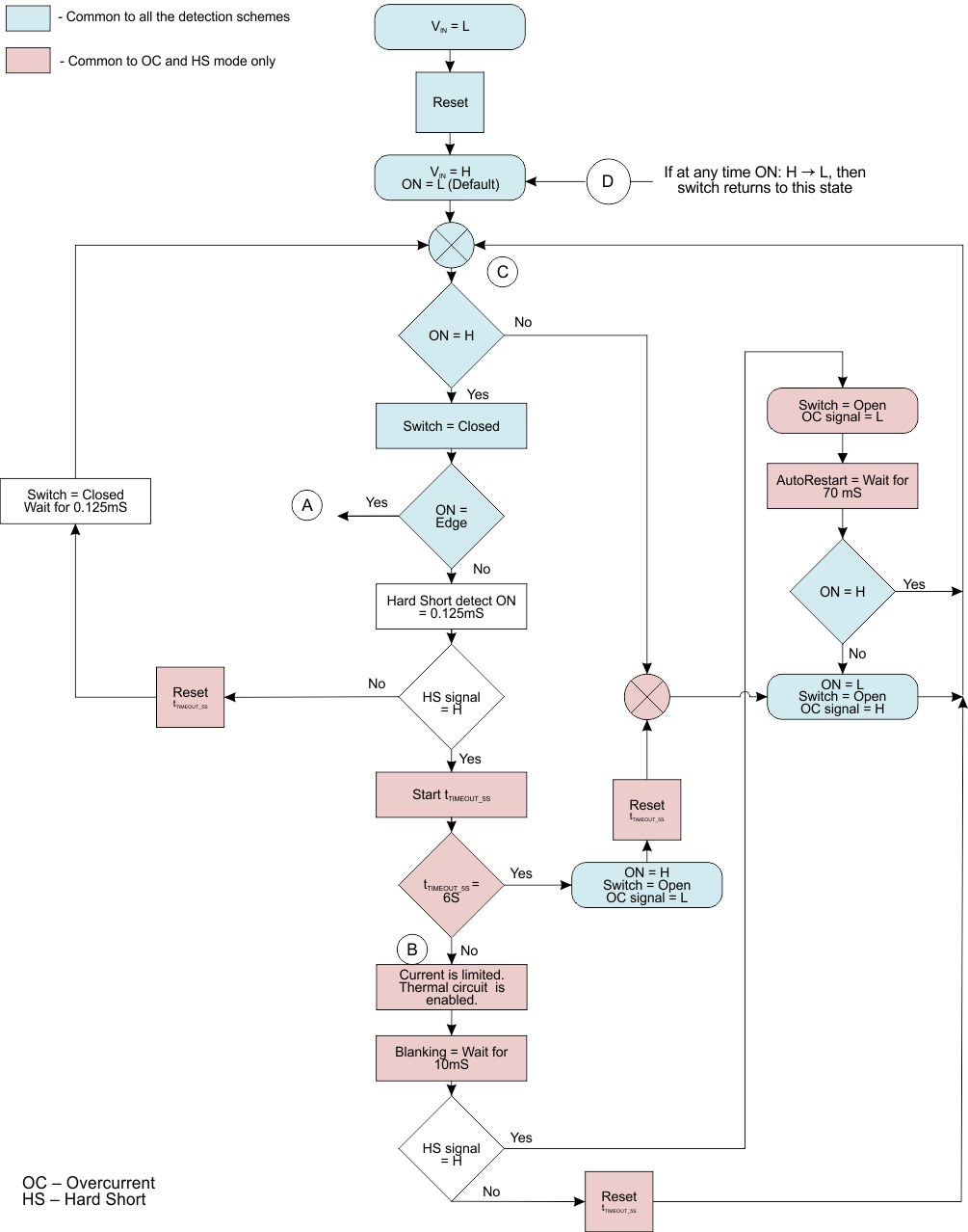 Figure 33. Hard Short-Circuit Detection Flow Diagram