ZHCSP18A November 2021 – June 2022 TPS22953-Q1 , TPS22954-Q1
PRODUCTION DATA
- 1 特性
- 2 应用
- 3 说明
- 4 Revision History
- 5 Device Comparison Table
- 6 Pin Configuration and Functions
-
7 Specifications
- 7.1 Absolute Maximum Ratings
- 7.2 ESD Ratings
- Recommended Operating Conditions
- 7.3 Thermal Information
- 7.4 Electrical Characteristics
- 7.5 Electrical Characteristics – VBIAS = 5 V
- 7.6 Electrical Characteristics – VBIAS = 3.3 V
- 7.7 Electrical Characteristics – VBIAS = 2.5 V
- 7.8 Switching Characteristics – CT = 1000 pF
- 7.9 Switching Characteristics – CT = 0 pF
- 7.10 Typical DC Characteristics
- 7.11 Typical Switching Characteristics
- 8 Parameter Measurement Information
-
9 Detailed Description
- 9.1 Overview
- 9.2 Functional Block Diagram
- 9.3
Feature Description
- 9.3.1 On and Off Control (EN Pin)
- 9.3.2 Voltage Monitoring (SNS Pin)
- 9.3.3 Power Good (PG Pin)
- 9.3.4 Supervisor Fault Detection and Automatic Restart
- 9.3.5 Manual Restart
- 9.3.6 Thermal Shutdown
- 9.3.7 Reverse Current Blocking (TPS22953-Q1 Only)
- 9.3.8 Quick Output Discharge (QOD) (TPS22954-Q1 Only)
- 9.3.9 VIN and VBIAS Voltage Range
- 9.3.10 Adjustable Rise Time (CT Pin)
- 9.3.11 Power Sequencing
- 9.4 Device Functional Modes
- 10Application and Implementation
- 11Power Supply Recommendations
- 12Layout
- 13Device and Documentation Support
- 14Mechanical, Packaging, and Orderable Information
3 说明
TPS2295x-Q1 是具有受控导通功能的小型单通道负载开关。此类器件包含一个可在 0.7V 至 5.7V 输入电压范围内运行的 N 沟道 MOSFET,并且可支持高达 5A 的连续电流。
该器件具有可调欠压锁定 (UVLO) 和可调电源正常 (PG) 阈值,可提供电压监控和可靠的电源时序功能。该器件的可调上升时间控制可大大降低各种大容量负载电容的浪涌电流,从而降低或消除电源压降。开关由可与低压控制信号直接连接的开关输入 (EN) 单独控制。该器件集成了一个 15Ω 片上负载,以便在禁用开关时使输出快速放电。增强型快速输出放电 (QOD) 功能可在器件断电后的短时间内继续有效,以便使输出完成放电。
TPS2295x-Q1 采用小型、节省空间的 10-SON 封装,此类封装具有集成散热焊盘,可实现高功率耗散。该器件在自然通风环境下的额定运行温度范围为 –40°C 至 +125°C。
器件信息(1)
| 器件型号 | 封装(引脚) | 封装尺寸(标称值) |
|---|---|---|
| TPS2295x-Q1 | WSON (10) | 2.00mm × 3.00mm |
(1) 如需了解所有可用封装,请参阅数据表末尾的可订购米6体育平台手机版_好二三四附录。
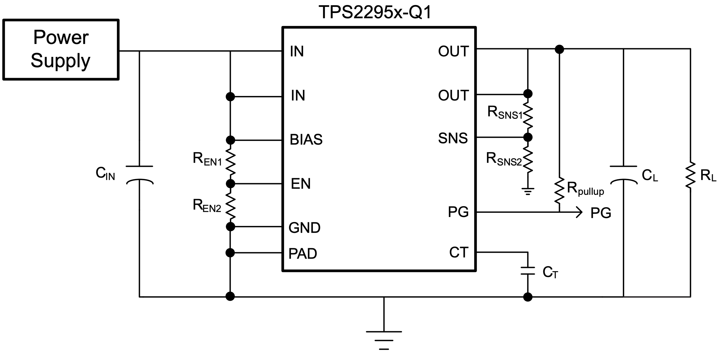
 简化版原理图