ZHCSCG6A May   2014  – December 2014 TPS2513A-Q1 , TPS2514A-Q1

PRODUCTION DATA.  

  1. 特性
  2. 应用范围
  3. 说明
  4. 简化应用示意图
  5. 修订历史记录
  6. Pin Configuration and Functions
  7. Specifications
    1. 7.1 Absolute Maximum Ratings
    2. 7.2 ESD Ratings
    3. 7.3 Recommended Operating Conditions
    4. 7.4 Thermal Information
    5. 7.5 Electrical Characteristics
    6. 7.6 Typical Characteristics
  8. Detailed Description
    1. 8.1 Overview
    2. 8.2 Functional Block Diagram
    3. 8.3 Feature Description
      1. 8.3.1 BC1.2
      2. 8.3.2 Undervoltage Lockout (UVLO)
      3. 8.3.3 DCP Auto-Detect
    4. 8.4 Device Functional Modes
      1. 8.4.1 Shorted Mode
      2. 8.4.2 Divider Mode
      3. 8.4.3 1.2 V Mode
  9. Applications and Implementation
    1. 9.1 Application Information
    2. 9.2 Typical Application
      1. 9.2.1 Design Requirements
      2. 9.2.2 Detailed Design Procedure
        1. 9.2.2.1 USB Power Switch
      3. 9.2.3 Application Curves
  10. 10Power Supply Recommendations
  11. 11Layout
    1. 11.1 Layout Guidelines
    2. 11.2 Layout Example
  12. 12器件和文档支持
    1. 12.1 相关链接
    2. 12.2 商标
    3. 12.3 静电放电警告
    4. 12.4 术语表
  13. 13机械封装和可订购信息

封装选项

机械数据 (封装 | 引脚)
散热焊盘机械数据 (封装 | 引脚)
订购信息

9 Applications and Implementation

9.1 Application Information

The device is a dual channel USB charging port controller. It can be used for automotive USB charging port to support universal charging.

9.2 Typical Application
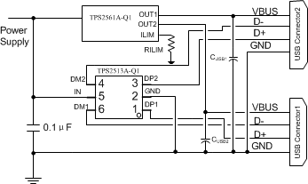
Specific_Application_slvscc8.gifFigure 12. Typical Application Schematic, Dual Ports Charger

9.2.1 Design Requirements

For dual USB ports, request that both ports support fast charge portable device compatible with divider 3, 1.2 V, and BC1.2 shorted mode.

9.2.2 Detailed Design Procedure

9.2.2.1 USB Power Switch

Some chargers requests that the USB port have an overcurrent protection when short circuits are encountered, TPS2561A-Q1 (SLVSCC6) is recommended.

The TPS2513A-Q1 divider 3 mode can support a maximum charging current up to 2.4 A.

When set, the TPS2561A-Q1 current limit (RILIM) should keep each channel current limit above 2.4 A. For the correct current limit setting, refer to the TPS2561A-Q1 data sheet.

9.2.3 Application Curves
C001_SLVSCC8.png
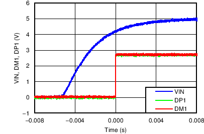
Figure 13. Power On (DM1 and DP1)
C003_SLVSCC8.png
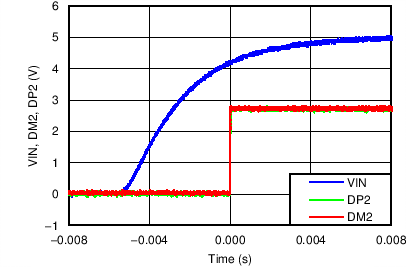
Figure 15. Power On (DM2 and DP2)
C002_SLVSCC8.png
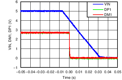
Figure 14. Power Off (DM1 and DP1)
C004_SLVSCC8.png
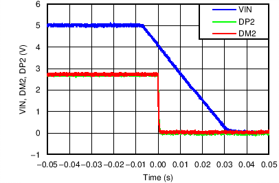
Figure 16. Power Off (DM2 and DP2)