ZHCSHI4D January   2018  – December 2019 TPS25221

PRODUCTION DATA.  

  1. 特性
  2. 应用
  3. 说明
    1.     Device Images
      1.      简化原理图
  4. 修订历史记录
  5. Device Comparison Table
  6. Pin Configuration and Functions
    1.     Pin Functions
  7. Specifications
    1. 7.1 Absolute Maximum Ratings
    2. 7.2 ESD Ratings
    3. 7.3 Recommended Operating Conditions
    4. 7.4 Thermal Information
    5. 7.5 Electrical Characteristics
    6. 7.6 Typical Characteristics
  8. Parameter Measurement Information
  9. Detailed Description
    1. 9.1 Overview
    2. 9.2 Functional Block Diagram
    3. 9.3 Feature Description
      1. 9.3.1 Over-current Conditions
      2. 9.3.2 Fault Response
      3. 9.3.3 Undervoltage Lockout (UVLO)
      4. 9.3.4 Enable, (EN)
      5. 9.3.5 Thermal Sense
    4. 9.4 Device Functional Modes
    5. 9.5 Programming
      1. 9.5.1 Programming the Current-Limit Threshold
  10. 10Application and Implementation
    1. 10.1 Application Information
      1. 10.1.1 Constant-Current
    2. 10.2 Typical Applications
      1. 10.2.1 Two-Level Current-Limit Circuit
        1. 10.2.1.1 Design Requirements
        2. 10.2.1.2 Detailed Design Procedures
          1. 10.2.1.2.1 Designing Above a Minimum Current Limit
          2. 10.2.1.2.2 Designing Below a Maximum Current Limit
          3. 10.2.1.2.3 Accounting for Resistor Tolerance
          4. 10.2.1.2.4 Input and Output Capacitance
        3. 10.2.1.3 Application Curve
      2. 10.2.2 Auto-Retry Functionality
        1. 10.2.2.1 Design Requirements (added)
        2. 10.2.2.2 Detailed Design Procedure
      3. 10.2.3 Typical Application as USB Power Switch
        1. 10.2.3.1 Design Requirements
          1. 10.2.3.1.1 USB Power-Distribution Requirements
        2. 10.2.3.2 Detailed Design Procedure
          1. 10.2.3.2.1 Universal Serial Bus (USB) Power-Distribution Requirements
  11. 11Power Supply Recommendations
    1. 11.1 Self-Powered and Bus-Powered Hubs
    2. 11.2 Low-Power Bus-Powered and High-Power Bus-Powered Functions
    3. 11.3 Power Dissipation and Junction Temperature
  12. 12Layout
    1. 12.1 Layout Guidelines
    2. 12.2 Layout Example
  13. 13器件和文档支持
    1. 13.1 器件支持
      1. 13.1.1 第三方米6体育平台手机版_好二三四免责声明
    2. 13.2 文档支持
      1. 13.2.1 相关文档
    3. 13.3 接收文档更新通知
    4. 13.4 社区资源
    5. 13.5 商标
    6. 13.6 静电放电警告
    7. 13.7 Glossary
  14. 14机械、封装和可订购信息

封装选项

机械数据 (封装 | 引脚)
散热焊盘机械数据 (封装 | 引脚)
订购信息

Typical Characteristics

See Figure 21 for reference schematic
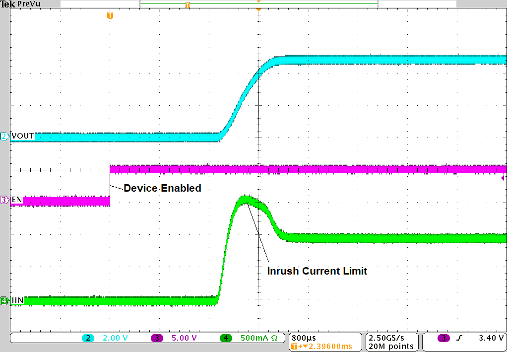
TPS25221 slvsdt3_turn_on_delay.png
VIN = 5 V, RILIM = 20 kΩ, ROUT = 5 Ω
Figure 5. Turnon Delay and Rise Time
TPS25221 slvsdt3_enable_to_short.png
VIN = 5 V, RILIM = 20 kΩ, ROUT = 0 Ω
Figure 7. Device Enabled into Short-Circuit
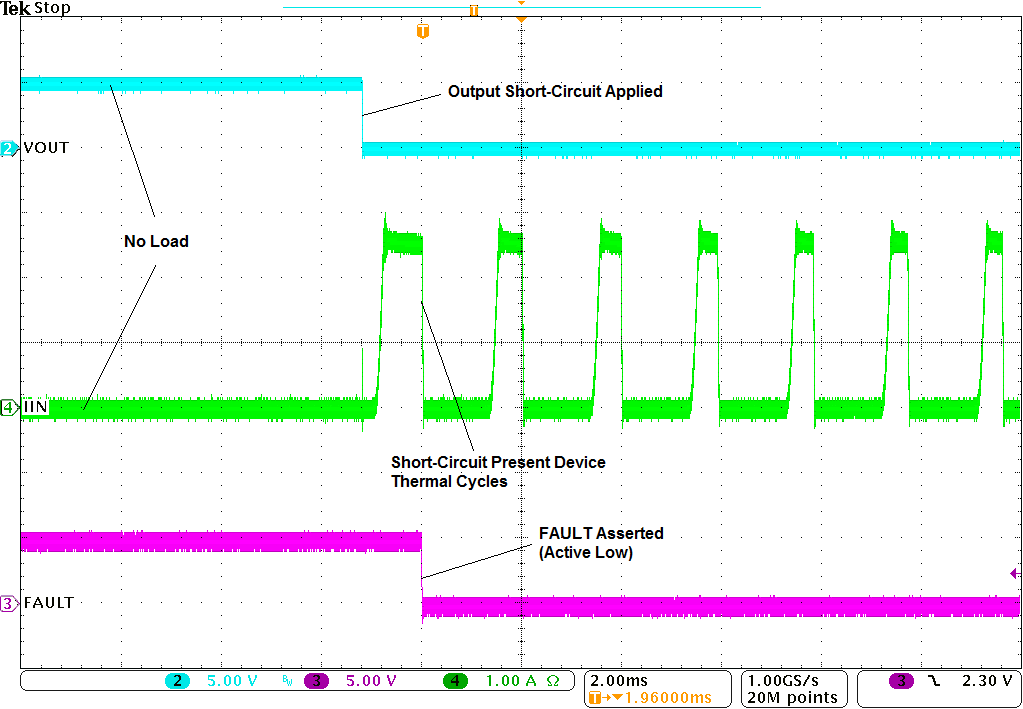
TPS25221 tek00028.png
VIN = 5 V, RILIM = 20 kΩ
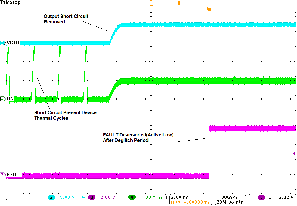
Figure 9. Short-Circuit to Full-Load Recovery Response
TPS25221 short_to_no_load2.png
VIN = 5 V, RILIM = 20 kΩ
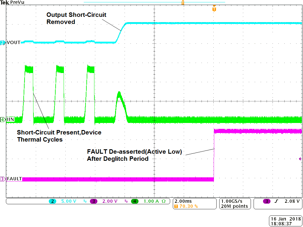
Figure 11. Short-Circuit to No-Load Recovery Response
TPS25221 1R_to_No_load.png
VIN = 5 V, RILIM = 20 kΩ
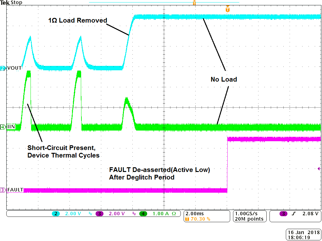
Figure 13. 1-Ω to No Load Transient Response
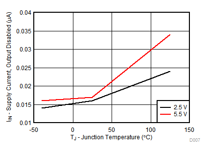
TPS25221 D007_new.gif
RILIM = 20 kΩ
Figure 15. IIN – Supply Current, Output Disabled – µA
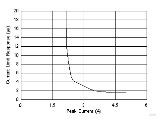
TPS25221 D006_SLVSDT3.gif
VIN = 5 V, RILIM = 20 kΩ, TA = 25°C
Figure 17. Current Limit Response – µs
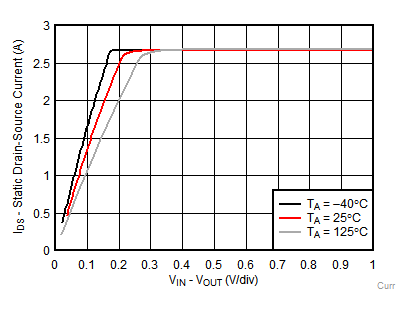
TPS25221 Currentlimit20K_new.gif
VIN = 5.5 V, RILIM = 20 kΩ
Figure 19. Switch Current Vs. Drain-Source Voltage Across Switch
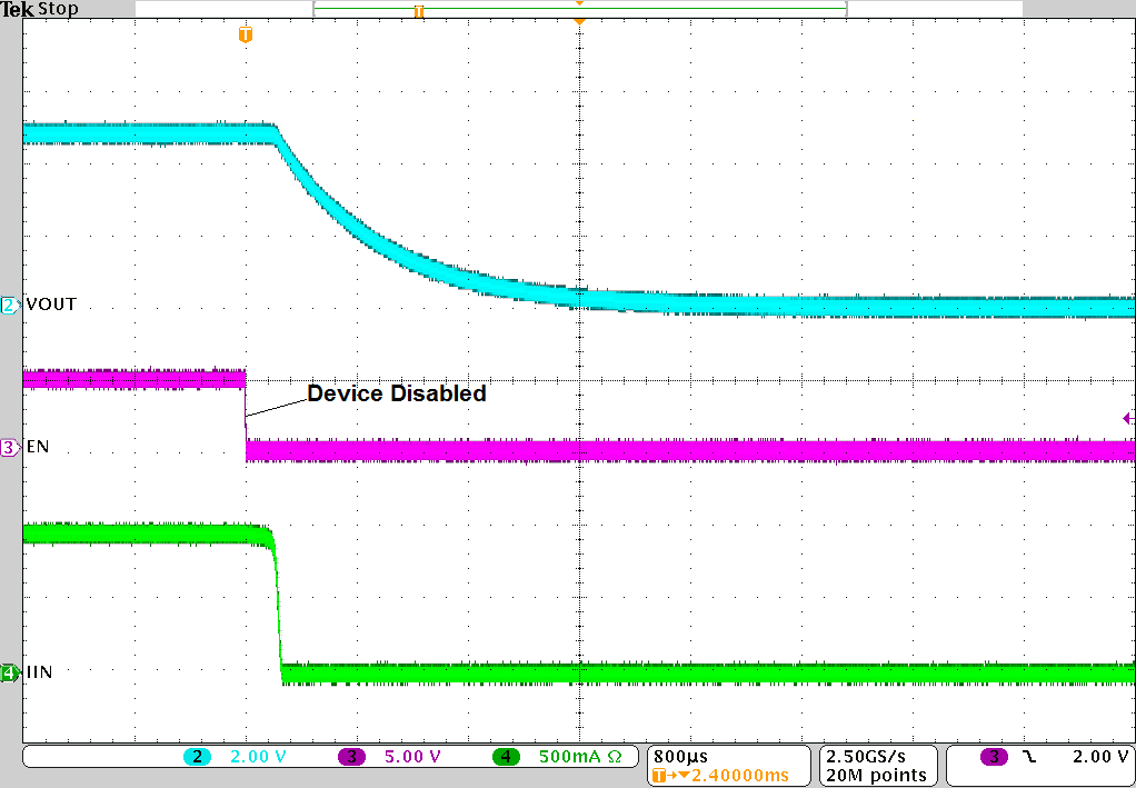
TPS25221 slvsdt3_turn_off_delay.png
VIN = 5 V, RILIM = 20 kΩ, ROUT = 5 Ω
Figure 6. Turnoff Delay and Fall Time
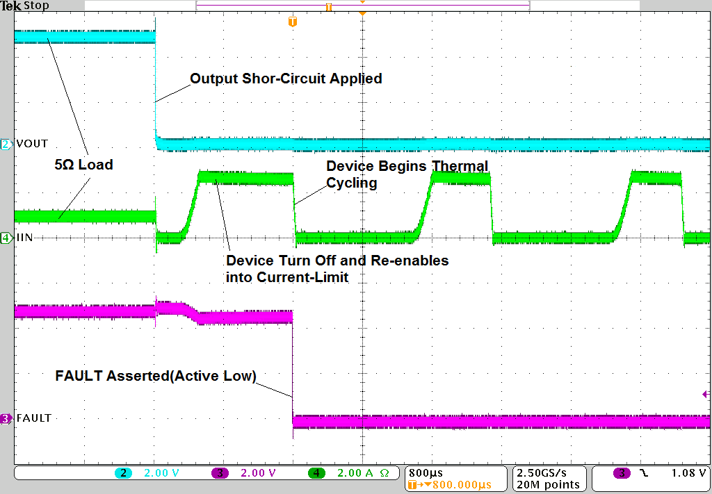
TPS25221 slvsdt3_full_load_to_short.png
VIN = 5 V, RILIM = 20 kΩ
Figure 8. Full-Load to Short-Circuit Transient Response
TPS25221 tek00034.png
VIN = 5 V, RILIM = 20 kΩ
Figure 10. No-Load to Short-Circuit Transient Response
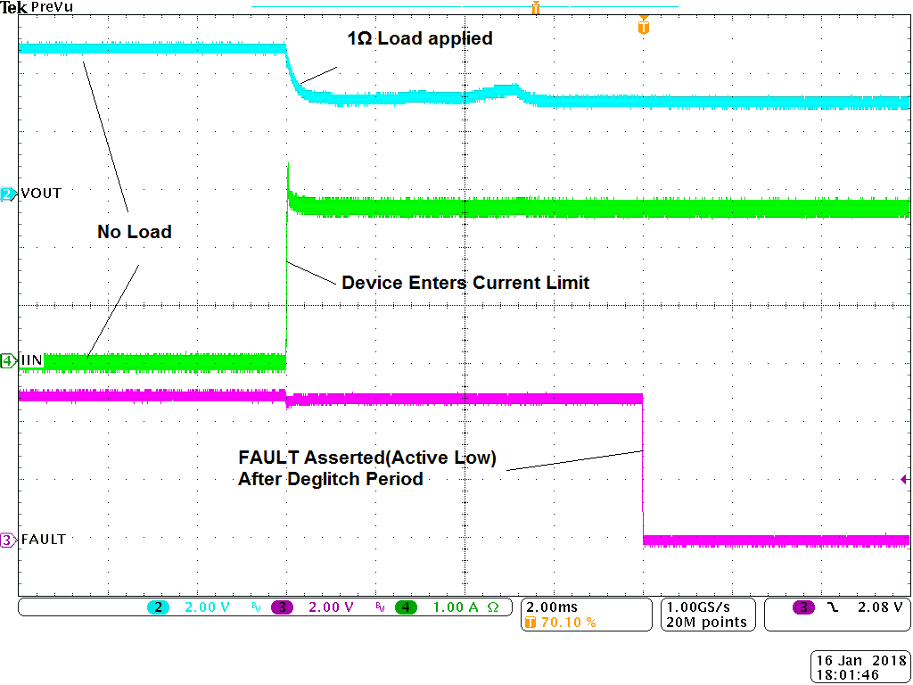
TPS25221 No_load_to_1R.png
VIN = 5 V, RILIM = 20 kΩ
Figure 12. No Load to 1-Ω Transient Response
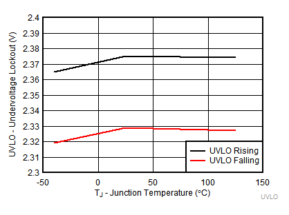
TPS25221 UVLO_6.gif
RILIM = 20 kΩ
Figure 14. UVLO – Undervoltage Lockout – V
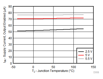
TPS25221 D008_new.gif
RILIM = 20 kΩ
Figure 16. IIN – Supply Current, Output Enabled – µA
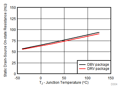
TPS25221 D004_new.gif
Figure 18. On-Resistance Vs. Junction Temperature
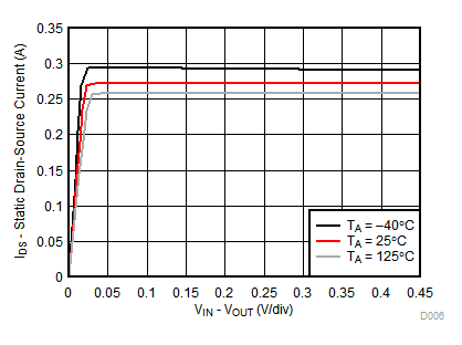
TPS25221 D006_new.gif
VIN = 5.5 V, RILIM = 210 kΩ
Figure 20. Switch Current Vs. Drain-Source Voltage Across Switch