ZHCSFH8D August 2016 – January 2018 TPS25741 , TPS25741A
UNLESS OTHERWISE NOTED, this document contains PRODUCTION DATA.
- 1 特性
- 2 应用
- 3 说明
- 4 修订历史记录
- 5 Device Comparison Table
- 6 Pin Configuration and Functions
- 7 Specifications
-
8 Detailed Description
- 8.1 Overview
- 8.2 Functional Block Diagram
- 8.3
Feature Description
- 8.3.1 USB Type-C CC Logic (CC1, CC2)
- 8.3.2 9.3.2 VCONN Supply (VCONN, CC1, CC2)
- 8.3.3 USB Power Delivery BMC Transmission (CC1, CC2, VTX)
- 8.3.4 USB Power Delivery BMC Reception (CC1, CC2)
- 8.3.5 Discharging (DSCG, VPWR)
- 8.3.6 Configuring Voltage Capabilities (HIPWR, EN9V, EN12V)
- 8.3.7 Configuring Power Capabilities (PSEL, PCTRL, HIPWR)
- 8.3.8 Gate Drivers
- 8.3.9 Fault Monitoring and Protection
- 8.3.10 Voltage Control (CTL1, CTL2)
- 8.3.11 Sink Attachment Indicator (UFP, DVDD)
- 8.3.12 Accessory Attachment Indicator (AUDIO, DEBUG)
- 8.3.13 Plug Polarity Indication (POL)
- 8.3.14 Power Supplies (VAUX, VDD, VPWR, DVDD)
- 8.3.15 Grounds (AGND, GND)
- 8.3.16 Output Power Supply (DVDD)
- 8.4 Device Functional Modes
- 9 Application and Implementation
- 10Power Supply Recommendations
- 11Layout
- 12器件和文档支持
- 13机械、封装和可订购信息
8.3.9.2 Over-Current Protection (ISNS, VBUS)
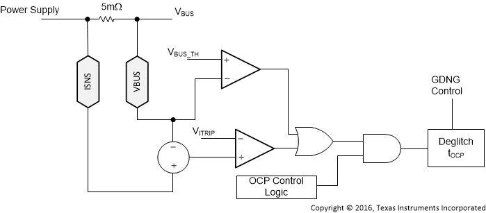
OCP protection is enabled tVP after the voltage on the VBUS pin has exceeded VBUS_RTH, see Figure 38. Prior to OCP being enabled, the GD pin can be used to protect against a short.
The OCP protection circuit monitors the differential voltage across an external sense resistor to detect when the current outflow exceeds VITRIP which in turn activates an over-current circuit breaker and disables the GDNG / GDNS gate driver. Once the OCP is enabled, if the voltage on the VBUS pin falls below VBUS_FTH then that is also treated like an OCP event.
Following the recommended implementation of a 5 mΩ sense resistor, when the device is configured to deliver 3 A (via HIPWR pin), the OCP threshold lies between 3.8 A and 4.5 A. When configured to deliver 5 A (via HIPWR pin), the OCP threshold lies between 5.8 A and 6.8 A. The sense resistor may be increased to tighten the OCP threshold.
 Figure 38. Overcurrent Protection Circuit