ZHCSFH8D August 2016 – January 2018 TPS25741 , TPS25741A
UNLESS OTHERWISE NOTED, this document contains PRODUCTION DATA.
- 1 特性
- 2 应用
- 3 说明
- 4 修订历史记录
- 5 Device Comparison Table
- 6 Pin Configuration and Functions
- 7 Specifications
-
8 Detailed Description
- 8.1 Overview
- 8.2 Functional Block Diagram
- 8.3
Feature Description
- 8.3.1 USB Type-C CC Logic (CC1, CC2)
- 8.3.2 9.3.2 VCONN Supply (VCONN, CC1, CC2)
- 8.3.3 USB Power Delivery BMC Transmission (CC1, CC2, VTX)
- 8.3.4 USB Power Delivery BMC Reception (CC1, CC2)
- 8.3.5 Discharging (DSCG, VPWR)
- 8.3.6 Configuring Voltage Capabilities (HIPWR, EN9V, EN12V)
- 8.3.7 Configuring Power Capabilities (PSEL, PCTRL, HIPWR)
- 8.3.8 Gate Drivers
- 8.3.9 Fault Monitoring and Protection
- 8.3.10 Voltage Control (CTL1, CTL2)
- 8.3.11 Sink Attachment Indicator (UFP, DVDD)
- 8.3.12 Accessory Attachment Indicator (AUDIO, DEBUG)
- 8.3.13 Plug Polarity Indication (POL)
- 8.3.14 Power Supplies (VAUX, VDD, VPWR, DVDD)
- 8.3.15 Grounds (AGND, GND)
- 8.3.16 Output Power Supply (DVDD)
- 8.4 Device Functional Modes
- 9 Application and Implementation
- 10Power Supply Recommendations
- 11Layout
- 12器件和文档支持
- 13机械、封装和可订购信息
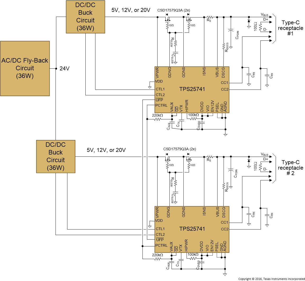
9.3.2 Dual-Port Power Managed A/C Power Source (Wall Adapter)
In this system design example, the PSEL is configured such that PSEL = 36 W, and only 5 V and 12 V are offered at a maximum of 3 A. The over-current protection (OCP) trip point is set just above 3 A.
The UFP pin from one TPS25741 is attached to the PCTRL pin on the other TPS25741. When one port is not active (no UFP attached through the receptacle) its UFP pin is left high-z so the PCTRL pin on the other port is pulled high. This allows the adaptor to provide up to the full 36 W on a single port if a single UFP is attached. If two UFP’s are attached (one to each port) then each port only offers current that would reach a maximum of 18 W. So each port is allocated half of the overall power when each port has a UFP attached.
 Figure 72. Dual-Port Adapter Provider Concept