ZHCSFF5G July 2016 – December 2019 TPS2660
PRODUCTION DATA.
- 1 特性
- 2 应用
- 3 说明
- 4 修订历史记录
- 5 Device Comparison Table
- 6 Pin Configuration and Functions
- 7 Specifications
- 8 Parameter Measurement Information
-
9 Detailed Description
- 9.1 Overview
- 9.2 Functional Block Diagram
- 9.3
Feature Description
- 9.3.1 Undervoltage Lockout (UVLO)
- 9.3.2 Overvoltage Protection (OVP)
- 9.3.3 Reverse Input Supply Protection
- 9.3.4 Hot Plug-In and In-Rush Current Control
- 9.3.5 Overload and Short Circuit Protection
- 9.4 Device Functional Modes
-
10Application and Implementation
- 10.1 Application Information
- 10.2
Typical Application
- 10.2.1 Design Requirements
- 10.2.2 Detailed Design Procedure
- 10.2.3 Application Curves
- 10.3 System Examples
- 10.4 Do's and Don'ts
- 11Power Supply Recommendations
- 12Layout
- 13器件和文档支持
- 14机械、封装和可订购信息
封装选项
请参考 PDF 数据表获取器件具体的封装图。
机械数据 (封装 | 引脚)
- RHF|24
- PWP|16
散热焊盘机械数据 (封装 | 引脚)
- PWP|16
订购信息
10.3.2 Field Supply Protection in PLC, DCS I/O Modules
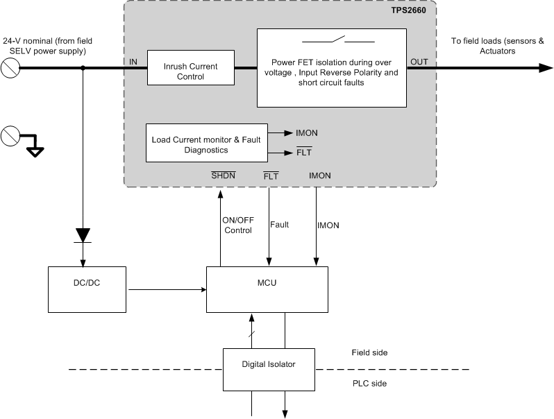
 Figure 68. Power Delivery Circuit Block Diagram in I/O Modules
 The PLC or Distributed Control System (DCS) I/O modules are often connected to an external field power supply to support higher power requirements of the field loads like sensors and actuators. Power-supply faults or miswiring can damage the loads or cause the loads not to operate correctly. The TPS2660x can be used as a front end protection circuit to protect and provide stable supply to the field loads. Under voltage, Over voltage and reverse polarity protection features of the TPS2660x prevent the loads to experience voltages outside the operating range, which can permanently damage the loads.
Field power supply is often connected to multiple I/O modules and is capable of delivering more current than a single I/O module can handle. Overcurrent protection scheme of the TPS2660x limits the current from the power supply to the module so that the maximum current does not rise above what the board is designed for. Fast short circuit protection scheme isolates the faulty load from the field supply quickly and prevents the field supply to dip and cause interrupts in the other I/O modules connected to the same field supply. High accurate (±5% at 1 A) current limit facilitates more I/O modules to be connected to field supply. Load current monitor (IMON) and fault indication (FLT) features facilitate continuous load monitoring.
The TPS2660x also acts as a smart diode with protection against reverse current during output side miswiring. Reverse current can potentially damage the field power supply and cause the I/O modules to run hot or may cause permanent damage.
If the field power supply is connected in reverse polarity (which is not unlikely as field power supplies are usually connected with screw terminals), field loads can permanently get damaged due to the reverse voltage. The reverse polarity protection feature of the TPS2660x prevents the reverse voltage to appear at the load side.