ZHCSMK7C November   2020  – December 2021 TPS2661

PRODUCTION DATA  

  1. 特性
  2. 应用
  3. 说明
  4. Revision History
  5. Device Comparison Table
  6. Pin Configuration and Functions
  7. Specifications
    1. 7.1 Absolute Maximum Ratings
    2. 7.2 ESD Ratings
    3. 7.3 Recommended Operating Conditions
    4. 7.4 Thermal Information
    5. 7.5 Electrical Characteristics
    6. 7.6 Timing Requirements
    7. 7.7 Typical Characteristics
  8. Detailed Description
    1. 8.1 Overview
    2. 8.2 Functional Block Diagram
    3. 8.3 Feature Description
      1. 8.3.1 Overload Protection and Fast-Trip
      2. 8.3.2 Reverse Current Blocking for Unipolar Current Inputs TPS26610, TPS26611 and TPS26612 (4–20 mA, 0–20 mA)
      3. 8.3.3 OUTPUT and INPUT Cutoff During Overvoltage, Undervoltage Due to Miswiring
        1. 8.3.3.1 Output Overvoltage With TPS2661x Devices
        2. 8.3.3.2 Output or Input Undervoltage With TPS26610, TPS26611 and TPS26612
        3. 8.3.3.3 Output Undervoltage With TPS26613 and TPS26614
      4. 8.3.4 External Power Supply (±Vs)
      5. 8.3.5 Loop Testing Without ±Vs Supply (Loop Power Mode in TPS26610, TPS26613 Only)
        1. 8.3.5.1 Supply Sensing With VSNS for Loop Power Mode With TPS26610 and TPS26613
      6. 8.3.6 Enable Control With TPS26611, TPS26612, and TPS26614
      7. 8.3.7 Signal Good Indicator (SGOOD)
    4. 8.4 Device Functional Modes
  9. Application and Implementation
    1. 9.1 Application Information
    2. 9.2 Typical Application: Analog Input Protection for Current Inputs with TPS26610
      1. 9.2.1 Design Requirements
      2. 9.2.2 Detailed Design Procedure for Current Inputs with TPS26610
        1. 9.2.2.1 Selecting ±Vs Supplies for TPS26610
        2. 9.2.2.2 Selecting RBurden
        3. 9.2.2.3 Selecting MODE Configuration for TPS26610
      3. 9.2.3 Application Performance Plots for Current Inputs with TPS26610
    3. 9.3 Typical Application: Analog Input Protection for Multiplexed Current and Voltage Inputs with TPS26611
      1. 9.3.1 Design Requirements
      2. 9.3.2 Detailed Design Procedure for Analog Input Protection for Multiplexed Current and Voltage Inputs with TPS26611
        1. 9.3.2.1 Selecting ±Vs Supplies for TPS26611
        2. 9.3.2.2 Selecting MODE Configuration for TPS26611
        3. 9.3.2.3 Selecting Bias Resistors R1, R2 for Setting Common Mode Voltage for Voltage Inputs
      3. 9.3.3 Application Performance Plots for V/I Inputs with TPS26611
    4. 9.4 System Examples
      1. 9.4.1 Power Supply Protection of 2-Wire Transmitter with TPS26612
      2. 9.4.2 Protection of 3-Wire Transmitters and Analog Output Modules With TPS26611, TPS26612
      3. 9.4.3 UART IO Protection With TPS26611, TPS26612
      4. 9.4.4 Higher Loop Impedance With TPS26613 and TPS26614
  10. 10Power Supply Recommendations
  11. 11Layout
    1. 11.1 Layout Guidelines
    2. 11.2 Layout Example
  12. 12Device and Documentation Support
    1. 12.1 接收文档更新通知
    2. 12.2 支持资源
    3. 12.3 Trademarks
    4. 12.4 Electrostatic Discharge Caution
    5. 12.5 术语表
  13. 13Mechanical, Packaging, and Orderable Information

封装选项

机械数据 (封装 | 引脚)
散热焊盘机械数据 (封装 | 引脚)
订购信息

说明

TPS2661x 是一款紧凑、功能丰富且完全集成的电流环路保护器,适用于模拟输入、模拟输出、传感器变送器、HART 输入和 UART IO 保护。该器件提供 ±20mA、0mA 至 20mA、4mA 至 20mA 的通用输入保护。7.5Ω 的低 RON 值可有效降低电流环路中的压降,从而扩展工作电压范围,即使在使用低压电源的情况下也可支持器件运行。该器件可以承受高达 ±50V 正负电源电压并保护负载免受影响。MODE 引脚提供了灵活性,可以使通过器件的电流限制翻倍,从而能够正确启动两个线控变送器。该器件能够使用低至 ±2.25V 至 ±20V 的外部双极性电源供电,还可以使用低至 3V 至 30V 的单极性电源供电。TPS26610 和 TPS26613 具有环路电源模式,便于在没有 ±Vs 电源的无电状态下进行环路测试。

该器件还通过关闭电流路径来保护系统,防止模拟输出和传感器变送器的输出侧误接线。TPS2661x 内部强大的保护控制模块以及 50V 额定电压有助于防止信号线的浪涌 (IEC61000-4-5) 和 EFT (IEC61000-4-4) 瞬变。该器件采用 2.9mm × 1.6mm 8 引脚 SOT-23 封装,大幅减小了系统占用空间。

器件信息(1)
器件型号 封装 封装尺寸(标称值)
TPS26610 SOT-23 (8) 2.9mm × 1.6mm
TPS26611
TPS26612
TPS26613
TPS26614
如需了解所有可用封装,请参阅数据表末尾的可订购米6体育平台手机版_好二三四附录。
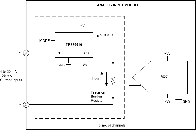
GUID-20201106-CA0I-QPXN-J60V-8H1MLLX6KF84-low.gif典型的电路原理图
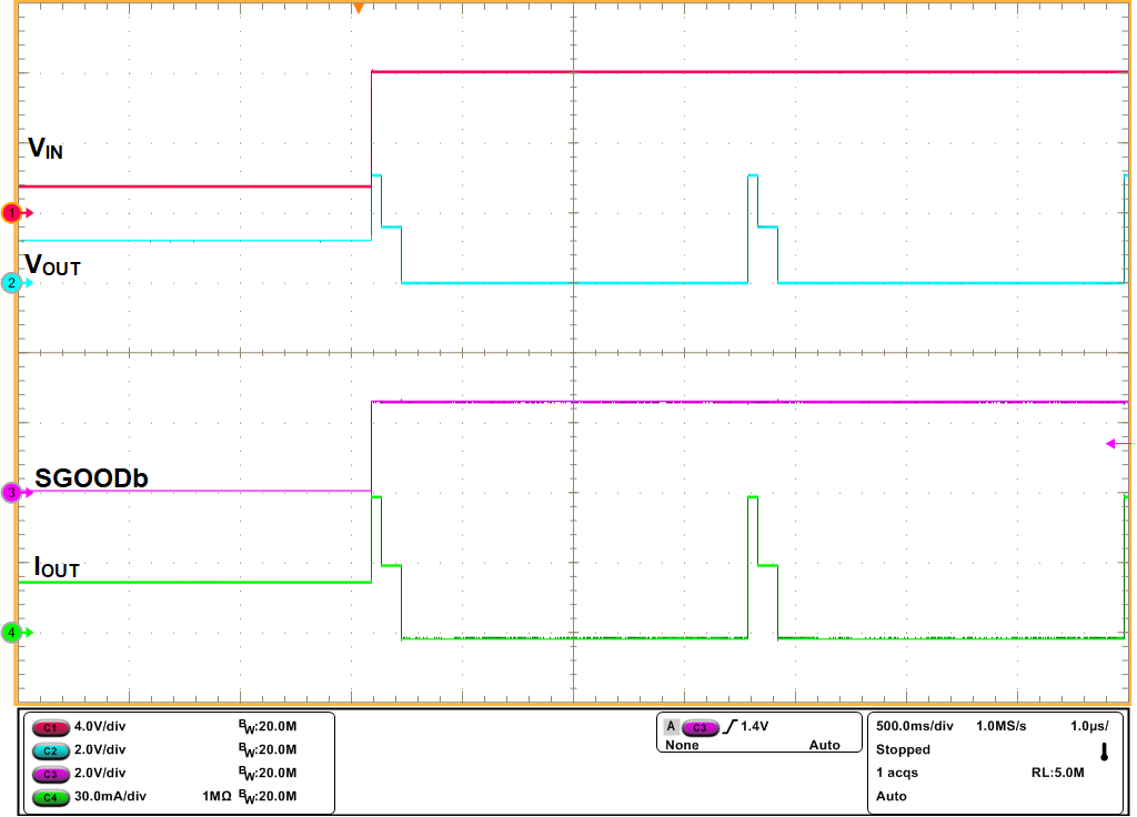
GUID-20201030-CA0I-MJKH-T08D-VKCQQ1G6SLPQ-low.png现场电源输入端的误接线保护