SLVSH67 September 2024 TPS26750
PRODUCTION DATA
- 1
- 1 Features
- 2 Applications
- 3 Description
- 4 Pin Configuration and Functions
-
5 Specifications
- 5.1 Absolute Maximum Ratings
- 5.2 ESD Ratings
- 5.3 Recommended Operating Conditions
- 5.4 Recommended Capacitance
- 5.5 Thermal Information
- 5.6 Power Supply Characteristics
- 5.7 Power Consumption
- 5.8 PP_5V Power Switch Characteristics
- 5.9 POWER_PATH_EN Characteristics - TPS26750
- 5.10 Power Path Supervisory
- 5.11 CC Cable Detection Parameters
- 5.12 CC VCONN Parameters
- 5.13 CC PHY Parameters
- 5.14 Thermal Shutdown Characteristics
- 5.15 ADC Characteristics
- 5.16 Input/Output (I/O) Characteristics
- 5.17 BC1.2 Characteristics
- 5.18 I2C Requirements and Characteristics
- 5.19 Typical Characteristics
- 6 Parameter Measurement Information
-
7 Detailed Description
- 7.1 Overview
- 7.2 Functional Block Diagram
- 7.3
Feature Description
- 7.3.1 USB-PD Physical Layer
- 7.3.2 Power Management
- 7.3.3 Power Paths
- 7.3.4 Cable Plug and Orientation Detection
- 7.3.5 Overvoltage Protection (CC1, CC2)
- 7.3.6 Default Behavior Configuration (ADCIN1, ADCIN2)
- 7.3.7 ADC
- 7.3.8 BC 1.2 (USB_P, USB_N)
- 7.3.9 Digital Interfaces
- 7.3.10 Digital Core
- 7.3.11 I2C Interface
- 7.4 Device Functional Modes
- 7.5 Thermal Shutdown
- 8 Application and Implementation
- 9 Device and Documentation Support
- 10Revision History
- 11Mechanical, Packaging, and Orderable Information
封装选项
请参考 PDF 数据表获取器件具体的封装图。
机械数据 (封装 | 引脚)
- RSM|32
散热焊盘机械数据 (封装 | 引脚)
- RSM|32
订购信息
7.3.6 Default Behavior Configuration (ADCIN1, ADCIN2)
This functionality is firmware controlled and subject to change.
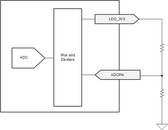
The ADCINx inputs to the internal ADC control the behavior of the TPS26750 in response to VBUS being supplied when VIN_3V3 is low (that is the dead-battery scenario). The ADCINx pins must be externally tied to the LDO_3V3 pin via a resistive divider as shown in the following figure. At power-up the ADC converts the ADCINx voltage and the digital core uses these two values to determine start-up behavior. The available start-up configurations include options for I2C target address of I2Ct_SCL/SDA, sink path control in dead-battery, and default configuration.
 Figure 7-13 ADCINx
Resistor Divider
Figure 7-13 ADCINx
Resistor DividerThe device behavior is determined in several ways depending upon the decoded value of the ADCIN1 and ADCIN2 pins. The following table shows the decoded values for different resistor divider ratios. See Pin Strapping to Configure Default Behavior for details on how the ADCINx configurations determine default device behavior. See I2C Address Setting for details on how ADCINx decoded values affects default I2C target address.
| DIV = RDOWN / (RUP + RDOWN)(1) | Without Using RUP or RDOWN | ADCINx Decoded Value(2) | ||
|---|---|---|---|---|
| MIN | Target | MAX | ||
| 0 | 0.0114 | 0.0228 | tie to GND | 0 |
| 0.0229 | 0.0475 | 0.0722 | N/A | 1 |
| 0.0723 | 0.1074 | 0.1425 | N/A | 2 |
| 0.1425 | 0.1899 | 0.2372 | N/A | 3 |
| 0.2373 | 0.3022 | 0.3671 | N/A | 4 |
| 0.3672 | 0.5368 | 0.7064 | tie to LDO_1V5 | 5 |
| 0.7065 | 0.8062 | 0.9060 | N/A | 6 |
| 0.9061 | 0.9530 | 1.0 | tie to LDO_3V3 | 7 |