ZHCSME3 November 2020 TPS27SA08
PRODUCTION DATA
- 1 特性
- 2 应用
- 3 说明
- 4 Revision History
- 5 Device Summary Table
- 6 Pin Configuration and Functions
- 7 Specifications
- 8 Parameter Measurement Information
-
9 Detailed Description
- 9.1 Overview
- 9.2 Functional Block Diagram
- 9.3
Feature Description
- 9.3.1 Protection Mechanisms
- 9.3.2 Diagnostic Mechanisms
- 9.4 Device Functional Modes
- 10Application and Implementation
- 11Power Supply Recommendations
- 12Layout
- 13Device and Documentation Support
- 14Mechanical, Packaging, and Orderable Information
10.2.3 Application Curves
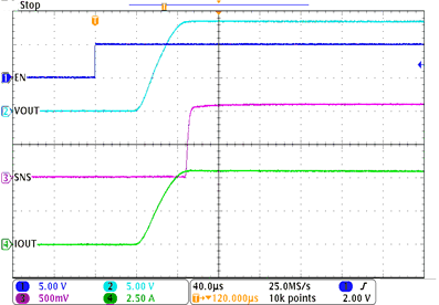
#T4593283-1 shows the behavior of the TPS27SA08 device in this application when the MCU provides an enable pulse to beginning heating the resistive element. Shortly after the EN pin goes high, the load current begins to flow and the SNS pin measures the output current.
 Figure 10-4 Heater Turn-on Time
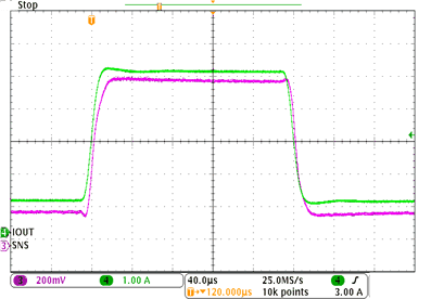
By measuring the voltage on the SNS pin, the TPS27SA08 device can communicate back to the system MCU what the load current is. #T4593283-2 shows that when the seat heater approaches full load and IOUT jumps from a low load current of 1 A up to a 5-A load current, the load step is mirrored on the SNS pin.
 Figure 10-5 SNS Response During Heater Load Step
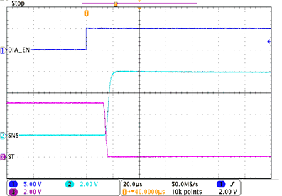
One common concern in these type of applications is that the heating element can accidentally lose connection, creating an open load situation. In this case, it is ideal for the TPS27SA08 device to recognize that the load has been removed and report a FLT to the MCU. #T4593283-3 shows the behavior of the TPS27SA08 device when there is no load attached. As soon as the DIAG_EN pin is engaged, the SNS output goes high and the ST output engages low. By monitoring these pins, the MCU can recognize there is a fault and notify the user that maintenance is required.
 Figure 10-6 Open Load Detection If Heating Element is Missing
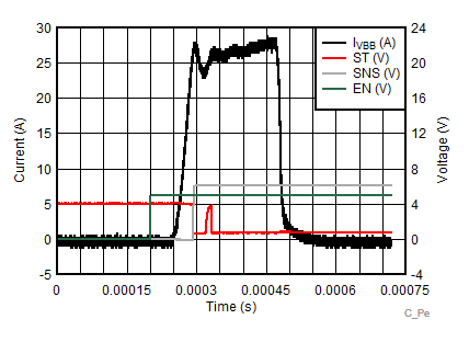
Importantly, the TPS27SA08 device will also protect the system in the event of a short-circuit. #T4593283-5 shows the behavior of the device if it is enabled into a short circuit condition. The current will be clamped to near the current limit threshold (ICL) until it hits an over temperature event, at which point the FET will be turned off. In this way, the system is protected from unchecked overcurrent in the event of a short circuit.
 Figure 10-7 Overcurrent Behavior During Short Circuit Event