ZHCSH96H MARCH   2007  – May 2019 TPS40192 , TPS40193

PRODUCTION DATA.  

  1. 特性
  2. 应用
  3. 说明
    1.     Device Images
      1.      简化应用示意图
  4. 修订历史记录
  5. Pin Configuration and Functions
    1.     Pin Functions
  6. Specifications
    1. 6.1 Absolute Maximum Ratings
    2. 6.2 ESD Ratings
    3. 6.3 Recommended Operating Conditions
    4. 6.4 Thermal Information
    5. 6.5 Electrical Characteristics
    6. 6.6 Dissipation Ratings
    7. 6.7 Typical Characteristics
  7. Detailed Description
    1. 7.1 Overview
    2. 7.2 Functional Block Diagram
    3. 7.3 Feature Description
      1. 7.3.1  Voltage Reference
      2. 7.3.2  Oscillator
      3. 7.3.3  UVLO
      4. 7.3.4  Enable Functionality
      5. 7.3.5  Start-Up Sequence and Timing
      6. 7.3.6  Selecting the Short Circuit Current
      7. 7.3.7  5-V Regulator
      8. 7.3.8  Prebias Start-Up
      9. 7.3.9  Drivers
      10. 7.3.10 Power Good
      11. 7.3.11 Thermal Shutdown
    4. 7.4 Device Functional Modes
      1. 7.4.1 Continuous Conduction Mode
      2. 7.4.2 Low-Quiescent Shutdown
  8. Application and Implementation
    1. 8.1 Application Information
    2. 8.2 Typical Application
      1. 8.2.1 Design Requirements
      2. 8.2.2 Detailed Design Procedure
        1. 8.2.2.1  Selecting the Switching Frequency
        2. 8.2.2.2  Inductor Selection
        3. 8.2.2.3  Output Capacitor Selection (C8)
        4. 8.2.2.4  Peak Current Rating of the Inductor
        5. 8.2.2.5  Input Capacitor Selection (C7)
        6. 8.2.2.6  MOSFET Switch Selection (Q1, Q2)
        7. 8.2.2.7  Boot Strap Capacitor
        8. 8.2.2.8  Input Bypass Capacitor (C6)
        9. 8.2.2.9  BP5 Bypass Capacitor (C5)
        10. 8.2.2.10 Input Voltage Filter Resistor (R11)
        11. 8.2.2.11 Short Circuit Protection (R9)
        12. 8.2.2.12 Feedback Compensation (Modeling the Power Stage)
        13. 8.2.2.13 Feedback Divider (R7, R8)
        14. 8.2.2.14 Error Amplifier Compensation (R6, R10, C1, C2, C3)
      3. 8.2.3 Application Curves
  9. Power Supply Recommendations
  10. 10Layout
    1. 10.1 Layout Guidelines
    2. 10.2 Layout Examples
  11. 11器件和文档支持
    1. 11.1 器件支持
      1. 11.1.1 开发支持
        1. 11.1.1.1 相关器件
      2. 11.1.2 器件命名规则
    2. 11.2 文档支持
    3. 11.3 相关链接
    4. 11.4 接收文档更新通知
    5. 11.5 社区资源
    6. 11.6 商标
    7. 11.7 静电放电警告
    8. 11.8 Glossary
  12. 12机械、封装和可订购信息

封装选项

机械数据 (封装 | 引脚)
散热焊盘机械数据 (封装 | 引脚)
订购信息

Application Curves

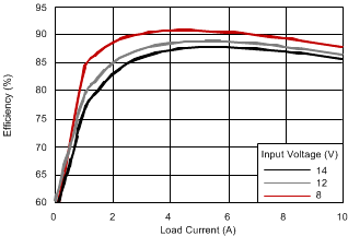
TPS40192 TPS40193 eff_vs_load_slus719.gifFigure 19. Efficiency vs. Output Current
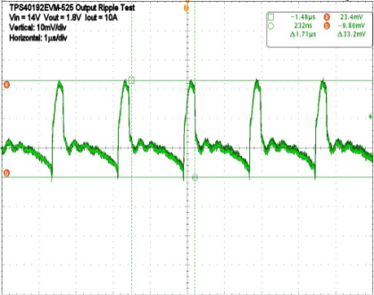
TPS40192 TPS40193 vo2_rip_luu395.gifFigure 21. Output Voltage Ripple
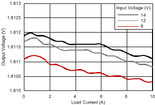
TPS40192 TPS40193 load_reg_slus719.gifFigure 20. Output Voltage Regulation
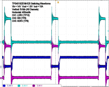
TPS40192 TPS40193 wf2_luu395.gifFigure 22. Switching Waveforms