SLUSAF8E July 2011 – January 2016 TPS40322
PRODUCTION DATA.
- 1 Features
- 2 Applications
- 3 Description
- 4 Revision History
- 5 Pin Configuration and Functions
- 6 Specifications
-
7 Detailed Description
- 7.1 Overview
- 7.2 Functional Block Diagram
- 7.3
Feature Description
- 7.3.1 Voltage Reference
- 7.3.2 Output Voltage Setting
- 7.3.3 Input Voltage Feedforward
- 7.3.4 Current Sensing
- 7.3.5 Overcurrent Protection
- 7.3.6 Two-Phase Mode, Remote Sense Amplifier, and Current Sharing Loop
- 7.3.7 Start-Up and Shutdown
- 7.3.8 Switching Frequency and Master or Slave Synchronization
- 7.3.9 Overvoltage and Undervoltage Fault Protection
- 7.3.10 Input Undervoltage Lockout (UVLO)
- 7.3.11 Power Good
- 7.3.12 Thermal Shutdown
- 7.3.13 Connection of Unused Pins
- 7.4 Device Functional Modes
-
8 Applications and Implementation
- 8.1 Application Information
- 8.2
Typical Applications
- 8.2.1
Dual-Output Configuration from 12-V Nominal to 1.2-V and 1.8-V DC-to-DC Converter Using the TPS40322
- 8.2.1.1 Design Requirements
- 8.2.1.2
Detailed Design Procedure
- 8.2.1.2.1 Selecting a Switching Frequency
- 8.2.1.2.2 Inductor Selection (L1)
- 8.2.1.2.3 Output Capacitor Selection (C10 through C16)
- 8.2.1.2.4 Peak Current Rating of Inductor
- 8.2.1.2.5 Input Capacitor Selection (C3 through C6)
- 8.2.1.2.6 MOSFET Selection (Q1)
- 8.2.1.2.7 ILIM Resistor (R2)
- 8.2.1.2.8 Feedback Divider (R10, R14)
- 8.2.1.2.9 Compensation: (R11, R12, C17, C19, C21)
- 8.2.1.2.10 Boot-Strap Capacitor (C7)
- 8.2.1.2.11
General Device Components
- 8.2.1.2.11.1 Synchronization (SYNC Pin)
- 8.2.1.2.11.2 RT Resistor (R6)
- 8.2.1.2.11.3 Differential Amplifier Out (DIFFO Pin)
- 8.2.1.2.11.4 EN/SS Timing Capacitors (C8)
- 8.2.1.2.11.5 Power Good (PG1, PG2 Pins)
- 8.2.1.2.11.6 Phase Set (PHSET Pin)
- 8.2.1.2.11.7 UVLO Programming Resistors (R1 and R3)
- 8.2.1.2.11.8 VDD Bypass Capacitor (C2)
- 8.2.1.2.11.9 VBP6 Bypass Capacitor (C18)
- 8.2.1.3 Application Curves
- 8.2.2 Two-Phase, Single Output Configuration from 12-V nominal to 1.2-V DC-to-DC Converter Using the TPS40322
- 8.2.1
Dual-Output Configuration from 12-V Nominal to 1.2-V and 1.8-V DC-to-DC Converter Using the TPS40322
- 9 Power Supply Recommendations
- 10Layout
- 11Device and Documentation Support
- 12Mechanical, Packaging, and Orderable Information
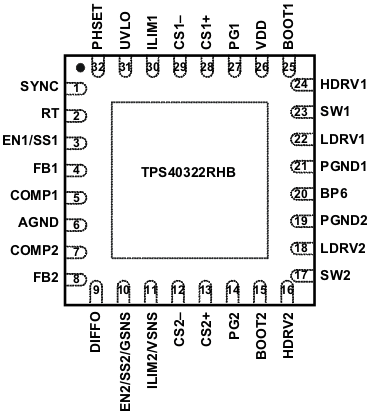
5 Pin Configuration and Functions
RHB Package
32-Pin VQFN
Top View

NOTE:
In two-phase mode, the EN2/SS2/GSNS pin becomes the GSNS pin and the ILIM2/VSNS pin becomes the VSNS pin.The two channels are identical unless specified otherwise.
The following naming conventions are used to better describe the functions. For example, COMPx refers to COMP1 and COMP2, FBx refers to FB1 and FB2.