ZHCSAP1D December   2012  – September 2014 TPS43060 , TPS43061

PRODUCTION DATA.  

  1. 特性
  2. 应用
  3. 说明
  4. 简化电路原理图
  5. 修订历史记录
  6. Pin Configuration and Functions
  7. Specifications
    1. 7.1 Absolute Maximum Ratings
    2. 7.2 Handling Ratings
    3. 7.3 Recommended Operating Conditions
    4. 7.4 Thermal Characteristics
    5. 7.5 Electrical Characteristics
    6. 7.6 Typical Characteristics
  8. Detailed Description
    1. 8.1 Overview
    2. 8.2 Functional Block Diagram
    3. 8.3 Feature Description
      1. 8.3.1  Switching Frequency
      2. 8.3.2  Low-Dropout Regulator
      3. 8.3.3  Input Undervoltage (UV)
      4. 8.3.4  Enable and Adjustable UVLO
      5. 8.3.5  Voltage Reference and Setting Output Voltage
      6. 8.3.6  Minimum On-Time and Pulse Skipping
      7. 8.3.7  Zero-Cross Detection and Duty Cycle
      8. 8.3.8  Minimum Off-Time and Maximum Duty Cycle
      9. 8.3.9  Soft-Start
      10. 8.3.10 Power Good
      11. 8.3.11 Overvoltage Protection (OVP)
      12. 8.3.12 OVP and Current Sense Resistor Selection
      13. 8.3.13 Gate Drivers
      14. 8.3.14 Thermal Shutdown
    4. 8.4 Device Functional Modes
      1. 8.4.1 Typical Operation (VIN < VOUT)
      2. 8.4.2 Pass Through (VIN > VOUT)
      3. 8.4.3 Split-Rail Operation
  9. Application and Implementation
    1. 9.1 Application Information
    2. 9.2 Typical Applications
      1. 9.2.1 Synchronous Boost Converter Typical Application Using TPS43061
        1. 9.2.1.1 Design Requirements
        2. 9.2.1.2 Detailed Design Procedure
          1. 9.2.1.2.1  Selecting the Switching Frequency
          2. 9.2.1.2.2  Inductor Selection
          3. 9.2.1.2.3  Selecting the Current Sense Resistor
          4. 9.2.1.2.4  Output Capacitor Selection
          5. 9.2.1.2.5  MOSFET Selection - NexFET Power Block
          6. 9.2.1.2.6  Bootstrap Capacitor Selection
          7. 9.2.1.2.7  VCC Capacitor
          8. 9.2.1.2.8  Input Capacitor
          9. 9.2.1.2.9  Output Voltage and Feedback Resistors Selection
          10. 9.2.1.2.10 Setting the Soft-Start Time
          11. 9.2.1.2.11 UVLO Set Point
          12. 9.2.1.2.12 Power Good Resistor Selection
          13. 9.2.1.2.13 Control Loop Compensation
          14. 9.2.1.2.14 DCM, Pulse-Skip Mode, and No-Load Input Current
        3. 9.2.1.3 Application Curves
      2. 9.2.2 High-Efficiency 40-V Synchronous Boost Converter Typical Application Using TPS43060
        1. 9.2.2.1 Design Requirements
        2. 9.2.2.2 Detailed Design Procedure
        3. 9.2.2.3 Application Curve
  10. 10Power Supply Recommendations
  11. 11Layout
    1. 11.1 Layout Guidelines
    2. 11.2 Layout Example
    3. 11.3 Thermal Considerations
  12. 12器件和文档支持
    1. 12.1 器件支持
      1. 12.1.1 Third-Party Products Disclaimer
    2. 12.2 相关链接
    3. 12.3 商标
    4. 12.4 静电放电警告
    5. 12.5 Glossary
  13. 13机械、封装和可订购信息

封装选项

机械数据 (封装 | 引脚)
散热焊盘机械数据 (封装 | 引脚)
订购信息

7 Specifications

7.1 Absolute Maximum Ratings

over operating free-air temperature (unless otherwise noted)
MIN MAX UNIT
Voltage Input: VIN, EN, ISNS+, ISNS– –0.3 40 V
DC voltage: SW –0.6 60 V
Transient voltage (10 ns max): SW –2 60 V
FB, RT/CLK, COMP, SS –0.3 3.6 V
BOOT, HDRV voltage with respect to ground 65 V
BOOT, HDRV voltage with respect to SW pin 8 V
VCC, PGOOD, LDRV –0.3 8 V
Operating junction temperature –40 150 °C

7.2 Handling Ratings

MIN MAX UNIT
Tstg Storage temperature range –65 150 °C
V(ESD) Electrostatic discharge Human body model (HBM), per ANSI/ESDA/JEDEC JS-001, all pins(1) –2000 2000 V
Charged device model (CDM), per JEDEC specification JESD22-C101, all pins(2) –500 500
(1) JEDEC document JEP155 states that 500-V HBM allows safe manufacturing with a standard ESD control process.
(2) JEDEC document JEP157 states that 250-V CDM allows safe manufacturing with a standard ESD control process.

7.3 Recommended Operating Conditions

over operating free-air temperature range (unless otherwise noted)
MIN NOM MAX UNIT
VIN Input voltage range 4.5 38 V
VOUT Output voltage range VIN 58 V
VEN EN voltage range 0 38 V
VCLK External switching frequency logic input range 0 3.6 V
TJ Operating junction temperature –40 150 °C

7.4 Thermal Characteristics

over operating free-air temperature range (unless otherwise noted)
THERMAL METRIC (1) WQFN
(16-PINS)
UNIT
RθJA Junction-to-ambient thermal resistance 65.7 °C/W
RθJC(top) Junction-to-case (top) thermal resistance 42.3
RθJB Junction-to-board thermal resistance 18
ψJT Junction-to-top characterization parameter 0.9
ψJB Junction-to-board characterization parameter 17.9
RθJC(bot) Junction-to-case (bottom) thermal resistance 22.7
(1) For more information about traditional and new thermal metrics, see the IC Package Thermal Metrics application report, SPRA953.

7.5 Electrical Characteristics

VIN = 4.5 to 38 V, TJ = –40ºC to 150ºC, unless otherwise noted. Typical values are at TA = 25ºC
PARAMETER TEST CONDITIONS MIN TYP MAX UNIT
SUPPLY AND ENABLE
VIN Input voltage range 4.5 38 V
VUV Input undervoltage threshold VIN falling 3.7 3.9 4 V
VIN rising 3.9 4.1 4.3 V
Vhys Undervoltage lockout hysteresis 200 mV
IQ Operating quiescent current into VIN Device non-switching,
RT = 115 kΩ, VFB = 2 V
600 800 µA
ISD Shutdown current VEN = 0.4 V 1.5 5 µA
VEN EN pin voltage threshold to standby VEN ramping down 0.4 0.7 0.9 V
EN pin voltage threshold to enable the device VEN ramping up 1.12 1.21 1.29 V
EN pin voltage threshold to disable the device VEN ramping down 1 1.14 1.28 V
IEN EN pin pullup current VEN = 1 V 1.8 µA
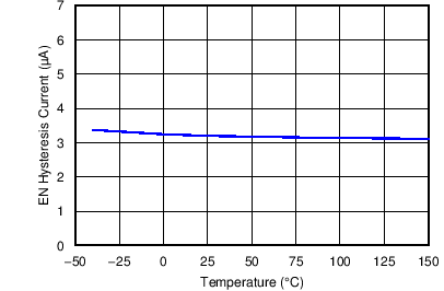
EN pin hysteresis current VEN = 1.3 V 3.2 4.6 µA
tEN EN to start switching time CVCC = 0.47 µF 125 µs
VCC VCC voltage TPS43060 VIN = 12 to 38 V,
IVCC = 0 µA
7.5 V
VIN = 4.5 V,
IVCC = 0 µA
4.5 V
TPS43061 VIN = 12 to 38 V,
IVCC = 0 µA
5.5 V
VIN = 4.5 V,
IVCC = 0 µA
4.5 V
IVCC VCC pin maximum output current 50 mA
VOLTAGE REFERENCE AND ERROR AMPLIFIER
VREF Feedback voltage reference TJ = 25°C 1.21 1.22 1.23 V
TJ = –40°C to 150°C 1.195 1.22 1.244
IFB Error amplifier input bias current 20 nA
ICOMP COMP pin sink current VFB = VREF + 250 mV, VCOMP = 1.5 V 160 µA
COMP pin source current VFB = VREF – 250 mV, VCOMP = 1.5 V 160 µA
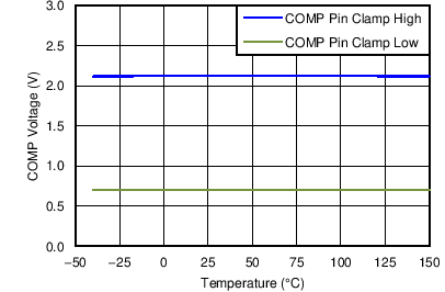
VCLAMP COMP pin clamp voltage High clamp, VFB = 1 V 2.1 V
Low clamp, VFB = 1.5 V 0.7
COMP pin threshold Duty cycle = 0% 1 V
Gea Error amplifier transconductance 1.1 mS
Rea Error amplifier output resistance 10
Fea Error amplifier crossover frequency 2 MHz
CURRENT SENSE
VCSmax Maximum current sense threshold At 0% duty cycle 64 73 82 mV
Maximum current sense threshold At max duty cycle 50 61 72 mV
VRCsns Reverse current sense threshold 3.8 mV
ISNS+ Sense+ pin current 70 µA
ISNS– Sense– pin current 70 µA
RT/CLK
ƒSW Switching frequency Operating frequency range using resistor timing mode 50 1000 kHz
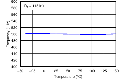
RT = 115 kΩ 450 500 550 kHz
RT = 75 kΩ 675 750 825 kHz
VRT/CLK RT/CLK pin voltage 0.5 V
tCLK-min Minimum input clock pulse duration PLL = 500 kHz 14 60 ns
vCLK-H RT/CLK high threshold 1.78 2 V
ƒCLK RT/CLK low threshold 0.4 1.35 V
PLL frequency sync range 300 1000 kHz
tPLLIN PLL lock in time 100 250 µs
tPLLEXIT Last RT/CLK falling edge to return to resistor timing mode if CLK is not present 140 250 µs
POWER SWITCH DRIVERS
RLDRV LDRV pullup resistance TPS43060 VIN = 12 to 40 V 2 Ω
VIN = 4.5 V 3
TPS43061 VIN = 12 to 40 V 2.5 Ω
VIN = 4.5 V 3
LDRV pulldown resistance TPS43060 VIN = 12 to 40 V 1.2 Ω
VIN = 4.5 V 2
TPS43061 VIN = 12 to 40 V 1.6 Ω
VIN = 4.5 V 2
RHDRV HDRV pullup resistance TPS43060 VIN = 12 to 40 V 2 Ω
VIN = 4.5 V 2.8
TPS43061 VIN = 12 to 40 V 5 Ω
VIN = 4.5 V 5.5
HDRV pulldown resistance TPS43060 VIN = 12 to 40 V 1.2 Ω
VIN = 4.5 V 1.9
TPS43061 VIN = 12 to 40 V 3 Ω
VIN = 4.5 V 3.7
tHR High-side gate rise time, 10% to 90% TPS43060 CLOAD = 2.2 nF,
VIN = 12 to 40 V
15 ns
TPS43061 20
tHF High-side gate fall time, 90% to 10% TPS43060 CLOAD = 2.2 nF,
VIN = 12 to 40 V
10 ns
TPS43061 15
tLR Low-side gate rise time, 10% to 90% TPS43060 CLOAD = 2.2 nF,
VIN = 12 to 40 V
15 ns
TPS43061 20
tLF Low-side gate fall time, 90% to 10% TPS43060 CLOAD = 2.2 nF,
VIN = 12 to 40 V
10 ns
TPS43061 15
VF BOOT diode forward voltage drop TPS43061 IF = 10 mA, TA = 25ºC 0.75 V
IBOOT BOOT pin leakage current TPS43061 Vr = 60 V 0.1 µA
tON LDRV minimum on pulse duration ƒSW = 500 kHz 100 ns
tOFF LDRV minimum off pulse duration ƒSW = 500 kHz 250 ns
tdelay Time delay between LDRV fall(50%) to HDRV rise (50%), tnon-overlap1 TPS43060,
CLOAD = open,
ƒSW = 500 kHz
VIN = 12 V 65 ns
VIN = 4.5 V 75 ns
TPS43061,
CLOAD = open,
ƒSW = 500 kHz
VIN = 12 V 65 ns
VIN = 4.5 V 75 ns
Time delay between HDRV fall (50%) to LDRV rise (50%), tnon-overlap2 TPS43060,
CLOAD = open,
ƒSW = 500 kHz
VIN = 12 V 65 ns
VIN = 4.5 V 75 ns
TPS43061,
CLOAD = open,
ƒSW = 500 kHz
VIN = 12 V 65 ns
VIN = 4.5 V 75 ns
POWER GOOD, SS AND OVP
PGDL PGOOD low threshold VFB with respect to feedback voltage reference, VFB falling 86% 90% 93%
PGOOD low hysteresis VFB with respect to feedback voltage reference 2%
PGDH PGOOD high threshold VFB with respect to feedback voltage reference, VFB rising 107% 110% 114%
PGOOD high hysteresis VFB with respect to feedback voltage reference 2%
PGDSC PGOOD sink current VPGOOD = 0.4 V 1.8 4 mA
PGDLK PGOOD pin leakage current VPGOOD = 7 V 100 nA
VIN_PGD Minimum VIN for valid PGOOD 2.5 4.3 V
ISS Soft-start bias current VSS = 0 V 5 µA
RSS Soft-start discharge resistance 250 Ω
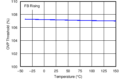
VOVP OVP threshold VFB with respect to feedback voltage reference, VFB rising 104% 107% 110%
OVP hysteresis VFB with respect to feedback voltage reference 2%
THERMAL SHUTDOWN
TSD Thermal shutdown set threshold 165 °C
Thyst Thermal shutdown hysteresis 15 °C

7.6 Typical Characteristics

VIN = 12 V, ƒSW = 500 kHz, TA = 25ºC (unless otherwise noted)
TPS43060 TPS43061 C002_SLVSBP4.png
Figure 1. Input Start and Stop Voltage vs Temperature
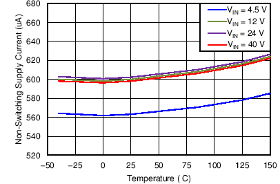
TPS43060 TPS43061 C004_SLVSBP4.png
Figure 3. Non-Switching Supply Current vs Temperature
TPS43060 TPS43061 C006_SLVSBP4.png
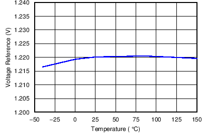
Figure 5. Feedback Voltage Reference vs Temperature
TPS43060 TPS43061 C008_SLVSBP4.png
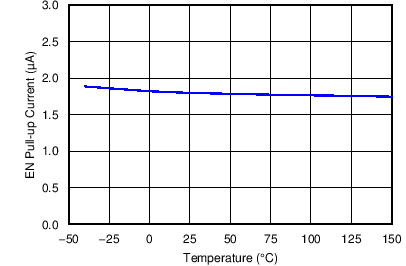
Figure 7. EN Pullup Current vs Temperature
TPS43060 TPS43061 C010_SLVSBP4.png
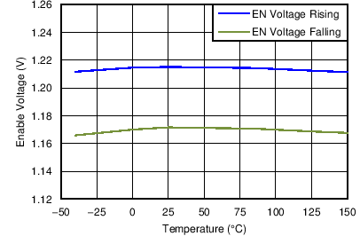
Figure 9. Enable Threshold vs Temperature
TPS43060 TPS43061 C012_SLVSBP4.png
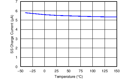
Figure 11. SS Charge Current vs Temperature
TPS43060 TPS43061 C014_SLVSBP4.png
Figure 13. OVP Threshold vs Temperature
TPS43060 TPS43061 C016_SLVSBP4.png
Figure 15. Reverse Current Sense Threshold vs Temperature
TPS43060 TPS43061 C003_SLVSBP4.png
Figure 2. Shutdown Supply Current vs Temperature
TPS43060 TPS43061 C005_SLVSBP4.png
Figure 4. Frequency vs Temperature
TPS43060 TPS43061 C007_SLVSBP4.png
Figure 6. COMP Clamp Voltage vs Temperature
TPS43060 TPS43061 C009_SLVSBP4.png
Figure 8. EN Hysteresis Current vs Temperature
TPS43060 TPS43061 C011_SLVSBP4.png
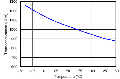
Figure 10. Error Amplifier Transconductance vs Temperature
TPS43060 TPS43061 C013_SLVSBP4.png
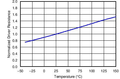
Figure 12. Gate Driver Output Resistance vs Temperature
TPS43060 TPS43061 C015_SLVSBP4.png
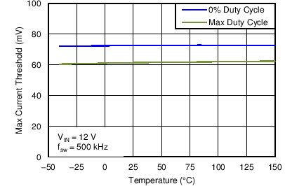
Figure 14. Maximum Current Sense Threshold vs Temperature
TPS43060 TPS43061 C017_SLVSBP4.png
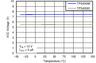
Figure 16. VCC Voltage vs Temperature