ZHCS189E June 2011 – December 2015 TPS43335-Q1 , TPS43336-Q1
PRODUCTION DATA.
- 1 特性
- 2 应用范围
- 3 说明
- 4 修订历史记录
- 5 Pin Configuration and Functions
- 6 Specifications
-
7 Detailed Description
- 7.1 Overview
- 7.2 Functional Block Diagram
- 7.3
Feature Description
- 7.3.1
Buck Controllers: Normal Mode PWM Operation
- 7.3.1.1 Frequency Selection and External Synchronization
- 7.3.1.2 Enable Inputs
- 7.3.1.3 Feedback Inputs
- 7.3.1.4 Soft-Start Inputs
- 7.3.1.5 Current-Mode Operation
- 7.3.1.6 Current Sensing and Current Limit With Foldback
- 7.3.1.7 Slope Compensation
- 7.3.1.8 Power-Good Outputs and Filter Delays
- 7.3.1.9 Light-Load PFM Mode
- 7.3.2 Boost Controller
- 7.3.3 Frequency-Hopping Spread Spectrum (TPS43336-Q1 Only)
- 7.3.4 Gate-Driver Supply (VREG, EXTSUP)
- 7.3.5 External P-Channel Drive (GC2) and Reverse Battery Protection
- 7.3.6 Undervoltage Lockout and Overvoltage Protection
- 7.3.7 Thermal Protection
- 7.3.1
Buck Controllers: Normal Mode PWM Operation
- 7.4 Device Functional Modes
-
8 Application and Implementation
- 8.1 Application Information
- 8.2
Typical Applications
- 8.2.1
Automotive Infotainment Supply
- 8.2.1.1 Design Requirements
- 8.2.1.2
Detailed Design Procedure
- 8.2.1.2.1 Boost Component Selection
- 8.2.1.2.2 Boost Maximum Input Current IIN_MAX
- 8.2.1.2.3 Boost Inductor Selection, L
- 8.2.1.2.4 Inductor Ripple Current, IRIPPLE
- 8.2.1.2.5 Peak Current in Low-Side FET, IPEAK
- 8.2.1.2.6 Right Half-Plane Zero RHP Frequency, fRHP
- 8.2.1.2.7 Output Capacitor, COUTx
- 8.2.1.2.8 Bandwidth of Boost Converter, fC
- 8.2.1.2.9 Output Ripple Voltage Due to Load Transients, ∆VOUTx
- 8.2.1.2.10 Selection of Components for Type II Compensation
- 8.2.1.2.11 Input Capacitor, CIN
- 8.2.1.2.12 Output Schottky Diode D1 Selection
- 8.2.1.2.13 Low-Side MOSFET (BOT_SW3)
- 8.2.1.2.14 BuckA Component Selection
- 8.2.1.2.15 Inductor Selection L
- 8.2.1.2.16 Inductor Ripple Current IRIPPLE
- 8.2.1.2.17 Output Capacitor COUTA
- 8.2.1.2.18 Bandwidth of Buck Converter fC
- 8.2.1.2.19 Selection of Components for Type II Compensation
- 8.2.1.2.20 Resistor Divider Selection for Setting VOUTA Voltage
- 8.2.1.2.21 BuckB Component Selection
- 8.2.1.2.22 Resistor Divider Selection for Setting VOUT Voltage
- 8.2.1.2.23 BuckX High-Side and Low-Side N-Channel MOSFETs
- 8.2.1.3 Application Curves
- 8.2.2 Automotive ADAS Supply
- 8.2.1
Automotive Infotainment Supply
- 9 Power Supply Recommendations
- 10Layout
- 11器件和文档支持
- 12机械、封装和可订购信息
1 特性
- 适用于汽车电子 应用
- 具有下列结果的 AEC-Q100 测试指南:
- 器件温度 1 级:-40°C 至 125°C 的环境运行温度范围
- 器件人体放电模式 (HBM) 静电放电 (ESD) 分类等级 H2
- 器件组件充电模式 (CDM) ESD 分类等级 C2
- 两个同步降压控制器
- 一个预升压控制器
- 当启用升压时,输入电压范围高达 40V,(瞬态电压高达 60V),运行电压低至 2V
- 低功耗模式 IQ:30µA(一个降压控制器打开),35µA(两个降压控制器打开)
- 低关断电流 Ish < 4µA
- 0.9V 至 11V 的降压输出范围
- 可选升压输出:7V,10V,或者 11V
- 可编程频率和外部同步范围为 150kHz 至 600kHz
- 独立的使能输入 (ENA,ENB)
- 频率展频 (TPS43336-Q1)
- 轻负载时,可选择强制持续模式或自动低功耗模式
- 感应电阻器或者电感器 DCR 感测
- 降压通道之间的反相开关
- 峰值栅极驱动电流 0.7A
- 耐热增强型 38 引脚散热薄型小外形尺寸封装 (HTSSOP)(DAP) PowerPAD™的 8 引脚小外形尺寸 (SO) 封装
2 应用范围
- 汽车启停、信息娱乐、导航仪表板系统
- 工业和汽车用多轨直流配电系统和电子控制单元
3 说明
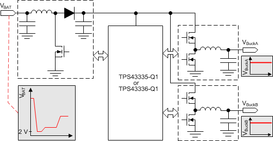
TPS43335-Q1 和 TPS43336-Q1 包含两个电流模式同步降压控制器和一个电压模式升压控制器。该器件非常适合用作 Iq 需求较低的前置稳压器, 适用于 必须抑制因启动事件所引起压降的应用。集成升压控制器允许器件在输入低至 2V 的条件下运行,同时不会导致降压稳压器输出级下降。在轻负载时,可以启用降压控制器来在自动低功耗模式下运行,消耗的静态电流仅为 30μA。
降压转换器有独立的软启动功能和电源正常指示器。降压控制器中的电流折返和升压控制器中的逐周期电流限制提供了外部金属氧化物半导体场效应晶体管 (MOSFET) 保护。用户可以在 150kHz 至 600kHz 的范围内设定开关频率,或者将其同步至同一范围内的外部时钟。此外,TPS43336-Q1 提供跳频扩频操作。
器件信息(1)
| 器件型号 | 封装 | 封装尺寸(标称值) |
|---|---|---|
| TPS43335-Q1 | HTSSOP (38) | 6.20mm x 12.50mm |
| TPS43336-Q1 |
- 要了解所有可用封装,请参见数据表末尾的可订购米6体育平台手机版_好二三四附录。
典型应用图
