ZHCSN24A August 2019 – May 2021 TPS53676
PRODUCTION DATA
- 1 特性
- 2 应用
- 3 说明
- 4 Revision History
- 5 Pin Configuration and Functions
-
6 Specifications
- 6.1 Absolute Maximum Ratings
- 6.2 Recommended Operating Conditions
- 6.3 ESD Ratings
- 6.4
Electrical Specifications
- 6.4.1 Thermal Information
- 6.4.2 Supply
- 6.4.3 DAC and Voltage Feedback
- 6.4.4 Control Loop Parameters
- 6.4.5 Dynamic VID (DVID) Tuning
- 6.4.6 Undershoot Reduction (USR) and Overshoot Reduciton (OSR)
- 6.4.7 Dynamic Phase Shedding (DPS)
- 6.4.8 Turbo Mode and Thermal Balance Management (TBM)
- 6.4.9 Overcurrent Limit (OCL)
- 6.4.10 Telemetry
- 6.4.11 Phase-Locked Loop and Closed-Loop Frequency Control
- 6.4.12 Logic Interface
- 6.4.13 Current Sensing and Current Sharing
- 6.4.14 Pin Detection Thresholds
- 6.4.15 ADDR Pinstrap Decoding
- 6.4.16 BOOT_CHA Pinstrap Decoding
- 6.4.17 Timing Specifications
- 6.4.18 Faults and Converter Protection
- 6.4.19 PMBus/AVS Interfaces
-
7 Detailed Description
- 7.1 Overview
- 7.2 Functional Block Diagram
- 7.3 Power-up and initialization
- 7.4
Pin connections and bevahior
- 7.4.1 Supplies: VCC and VREF
- 7.4.2 Differential remote sensing and output voltage scaling: AVSP/AVSN, BVSP/BVSN
- 7.4.3 Input current sensing: VIN_CSNIN and CSPIN
- 7.4.4 Pin-strap detection and PIN_DETECT_OVERRIDE
- 7.4.5 Enable and disable: AVR_EN and BVR_EN
- 7.4.6 System feedback: AVR_RDY and BVR_RDY
- 7.4.7 Catastrophic fault alert: VR_FAULT#
- 7.4.8 Output voltage reset: RESET#
- 7.4.9 Synchronization: SYNC
- 7.4.10 Smart power stage connections: PWM, CSP and TSEN
- 7.4.11 PMBus pins: SMB_DIO, SMB_CLK, and SMB_ALERT#
- 7.4.12 AVSBus: AVS_CLK, AVS_MDATA, AVS_SDATA, and AVS_VDDIO
- 7.5 Advanced power management functions
- 7.6
Control Loop Theory of Operation
- 7.6.1 Adaptive voltage positioning and DC load line (droop)
- 7.6.2 DCAP+ conceptual overview
- 7.6.3 Off-time control: loop compensation and transient tuning
- 7.6.4 On-time control: adaptive ton and autobalance current sharing
- 7.6.5 Load transient response
- 7.6.6 Forced minimum on-time, minimum off-time and leading-edge blanking time
- 7.6.7 Nonlinear: undershoot reduction (USR), overshoot reduction (OSR) and dynamic integration
- 7.7
Power supply fault protection
- 7.7.1 Host notification and status reporting
- 7.7.2 Fault type and response definitions
- 7.7.3 Fault behavior summary
- 7.7.4
Detailed fault descriptions
- 7.7.4.1 Overvoltage fault (OVF) and warning (OVW)
- 7.7.4.2 Undervoltage fault (UVF) and warning (UVW)
- 7.7.4.3 Maximum turn-on time exceeded (TON_MAX)
- 7.7.4.4 Output commanded out-of-bounds (VOUT_MIN_MAX)
- 7.7.4.5 Overcurrent fault (OCF), warning (OCW), and per-phase overcurrent limit (OCL)
- 7.7.4.6 Current share warning (ISHARE)
- 7.7.4.7 Overtemperature fault protection (OTF) and warning (OTW)
- 7.7.4.8 Powerstage fault (TAO_HIGH) and powerstage not ready (TAO_LOW)
- 7.7.4.9 Input overvoltage fault (VIN_OVF) and warning (VIN_OVW)
- 7.7.4.10 Input undervoltage fault (VIN_UVF), warning (VIN_UVW) and turn-on voltage (VIN_ON)
- 7.7.4.11 Input overcurrent fault (IIN_OCF) and warning (IIN_OCW)
- 7.7.4.12 Input overpower warning (PIN_OPW)
- 7.7.4.13 PMBus command, memory and logic errors (CML)
- 7.8
Programming
- 7.8.1
PMBus Interface
- 7.8.1.1 PMBus transaction types
- 7.8.1.2 PMBus data formats
- 7.8.1.3 Raw non-volatile memory programming
- 93
- 7.8.1.4
PMBus Command Descriptions
- 7.8.1.4.1 (00h) PAGE
- 7.8.1.4.2 (01h) OPERATION
- 7.8.1.4.3 (02h) ON_OFF_CONFIG
- 7.8.1.4.4 (03h) CLEAR_FAULTS
- 7.8.1.4.5 (04h) PHASE
- 7.8.1.4.6 (05h) PAGE_PLUS_WRITE
- 7.8.1.4.7 (06h) PAGE_PLUS_READ
- 7.8.1.4.8 (10h) WRITE_PROTECT
- 7.8.1.4.9 (15h) STORE_USER_ALL
- 7.8.1.4.10 (16h) RESTORE_USER_ALL
- 7.8.1.4.11 (19h) CAPABILITY
- 7.8.1.4.12 (1Bh) SMBALERT_MASK_WORD
- 7.8.1.4.13 (1Bh) SMBALERT_MASK_VOUT
- 7.8.1.4.14 (1Bh) SMBALERT_MASK_IOUT
- 7.8.1.4.15 (1Bh) SMBALERT_MASK_INPUT
- 7.8.1.4.16 (1Bh) SMBALERT_MASK_TEMPERATURE
- 7.8.1.4.17 (1Bh) SMBALERT_MASK_CML
- 7.8.1.4.18 (1Bh) SMBALERT_MASK_MFR
- 7.8.1.4.19 (20h) VOUT_MODE
- 7.8.1.4.20 (21h) VOUT_COMMAND
- 7.8.1.4.21 (22h) VOUT_TRIM
- 7.8.1.4.22 (24h) VOUT_MAX
- 7.8.1.4.23 (25h) VOUT_MARGIN_HIGH
- 7.8.1.4.24 (26h) VOUT_MARGIN_LOW
- 7.8.1.4.25 (27h) VOUT_TRANSITION_RATE
- 7.8.1.4.26 (28h) VOUT_DROOP
- 7.8.1.4.27 (29h) VOUT_SCALE_LOOP
- 7.8.1.4.28 (2Bh) VOUT_MIN
- 7.8.1.4.29 (33h) FREQUENCY_SWITCH
- 7.8.1.4.30 (34h) POWER_MODE
- 7.8.1.4.31 (35h) VIN_ON
- 7.8.1.4.32 (38h) IOUT_CAL_GAIN
- 7.8.1.4.33 (39h) IOUT_CAL_OFFSET
- 7.8.1.4.34 (40h) VOUT_OV_FAULT_LIMIT
- 7.8.1.4.35 (41h) VOUT_OV_FAULT_RESPONSE
- 7.8.1.4.36 (42h) VOUT_OV_WARN_LIMIT
- 7.8.1.4.37 (43h) VOUT_UV_WARN_LIMIT
- 7.8.1.4.38 (44h) VOUT_UV_FAULT_LIMIT
- 7.8.1.4.39 (45h) VOUT_UV_FAULT_RESPONSE
- 7.8.1.4.40 (46h) IOUT_OC_FAULT_LIMIT
- 7.8.1.4.41 (47h) IOUT_OC_FAULT_RESPONSE
- 7.8.1.4.42 (4Ah) IOUT_OC_WARN_LIMIT
- 7.8.1.4.43 (4Fh) OT_FAULT_LIMIT
- 7.8.1.4.44 (50h) OT_FAULT_RESPONSE
- 7.8.1.4.45 (51h) OT_WARN_LIMIT
- 7.8.1.4.46 (55h) VIN_OV_FAULT_LIMIT
- 7.8.1.4.47 (56h) VIN_OV_FAULT_RESPONSE
- 7.8.1.4.48 (57h) VIN_OV_WARN_LIMIT
- 7.8.1.4.49 (58h) VIN_UV_WARN_LIMIT
- 7.8.1.4.50 (59h) VIN_UV_FAULT_LIMIT
- 7.8.1.4.51 (5Ah) VIN_UV_FAULT_RESPONSE
- 7.8.1.4.52 (5Bh) IIN_OC_FAULT_LIMIT
- 7.8.1.4.53 (5Ch) IIN_OC_FAULT_RESPONSE
- 7.8.1.4.54 (5Dh) IIN_OC_WARN_LIMIT
- 7.8.1.4.55 (60h) TON_DELAY
- 7.8.1.4.56 (61h) TON_RISE
- 7.8.1.4.57 (62h) TON_MAX_FAULT_LIMIT
- 7.8.1.4.58 (63h) TON_MAX_FAULT_RESPONSE
- 7.8.1.4.59 (64h) TOFF_DELAY
- 7.8.1.4.60 (65h) TOFF_FALL
- 7.8.1.4.61 (6Bh) PIN_OP_WARN_LIMIT
- 7.8.1.4.62 (78h) STATUS_BYTE
- 7.8.1.4.63 (79h) STATUS_WORD
- 7.8.1.4.64 (7Ah) STATUS_VOUT
- 7.8.1.4.65 (7Bh) STATUS_IOUT
- 7.8.1.4.66 (7Ch) STATUS_INPUT
- 7.8.1.4.67 (7Dh) STATUS_TEMPERATURE
- 7.8.1.4.68 (7Eh) STATUS_CML
- 7.8.1.4.69 (80h) STATUS_MFR_SPECIFIC
- 7.8.1.4.70 (88h) READ_VIN
- 7.8.1.4.71 (89h) READ_IIN
- 7.8.1.4.72 (8Bh) READ_VOUT
- 7.8.1.4.73 (8Ch) READ_IOUT
- 7.8.1.4.74 (8Dh) READ_TEMPERATURE_1
- 7.8.1.4.75 (96h) READ_POUT
- 7.8.1.4.76 (97h) READ_PIN
- 7.8.1.4.77 (98h) PMBUS_REVISION
- 7.8.1.4.78 (99h) MFR_ID
- 7.8.1.4.79 (9Ah) MFR_MODEL
- 7.8.1.4.80 (9Bh) MFR_REVISION
- 7.8.1.4.81 (9Dh) MFR_DATE
- 7.8.1.4.82 (ADh) IC_DEVICE_ID
- 7.8.1.4.83 (AEh) IC_DEVICE_REV
- 7.8.1.4.84 (B1h) USER_DATA_01 (COMPENSATION_CONFIG)
- 7.8.1.4.85 (B2h) USER_DATA_02 (NONLINEAR_CONFIG)
- 7.8.1.4.86 (B3h) USER_DATA_03 (PHASE_CONFIG)
- 7.8.1.4.87 (B4h) USER_DATA_04 (DVID_CONFIG)
- 7.8.1.4.88 (B7h) USER_DATA_07 (PHASE_SHED_CONFIG)
- 7.8.1.4.89 (B8h) USER_DATA_08 (AVSBUS_CONFIG)
- 7.8.1.4.90 (BAh) USER_DATA_10 (ISHARE_CONFIG)
- 7.8.1.4.91 (BBh) USER_DATA_11 (MFR_PROTECTION_CONFIG)
- 7.8.1.4.92 (BDh) USER_DATA_13 (MFR_CALIBRATION_CONFIG)
- 7.8.1.4.93 (CDh) MFR_SPECIFIC_CD (MULTIFUNCTION_PIN_CONFIG_1)
- 7.8.1.4.94 (CEh) MFR_SPECIFIC_CD (MULTIFUNCTION_PIN_CONFIG_2)
- 7.8.1.4.95 (CFh) SMBALERT_MASK_EXTENDED
- 7.8.1.4.96 (D1h) READ_VOUT_MIN_MAX
- 7.8.1.4.97 (D2h) READ_IOUT_MIN_MAX
- 7.8.1.4.98 (D3h) READ_TEMPERATURE_MIN_MAX)
- 7.8.1.4.99 (D4h) READ_MFR_VOUT
- 7.8.1.4.100 (D5h) READ_VIN_MIN_MAX
- 7.8.1.4.101 (D6h) READ_IIN_MIN_MAX
- 7.8.1.4.102 (D7h) READ_PIN_MIN_MAX
- 7.8.1.4.103 (D8h) READ_POUT_MIN_MAX
- 7.8.1.4.104 (DAh) READ_ALL
- 7.8.1.4.105 (DBh) STATUS_ALL
- 7.8.1.4.106 (DCh) STATUS_PHASES
- 7.8.1.4.107 (DDh) STATUS_EXTENDED
- 7.8.1.4.108 (E0h) AVSBUS_LOG
- 7.8.1.4.109 (E3h) MFR_SPECIFIC_E3 (VR_FAULT_CONFIG)
- 7.8.1.4.110 (E4h) SYNC_CONFIG
- 7.8.1.4.111 (EDh) MFR_SPECIFIC_ED (MISC_OPTIONS)
- 7.8.1.4.112 (EEh) MFR_SPECIFIC_EE (PIN_DETECT_OVERRIDE)
- 7.8.1.4.113 (EFh) MFR_SPECIFIC_EF (SLAVE_ADDRESS)
- 7.8.1.4.114 (F0h) MFR_SPECIFIC_F0 (NVM_CHECKSUM)
- 7.8.1.4.115 (F5h) MFR_SPECIFIC_F5 (USER_NVM_INDEX)
- 7.8.1.4.116 (F6h) MFR_SPECIFIC_F6 (USER_NVM_EXECUTE)
- 7.8.1.4.117 (FAh) NVM_LOCK
- 7.8.1.4.118 (FBh) MFR_SPECIFIC_WRITE_PROTECT
- 7.8.2 AVSBus Interface
- 7.8.1
PMBus Interface
- 8 Applications and Implementation
- 9 Power Supply Recommendations
- 10Layout
- 11Device and Documentation Support
- 12Mechanical, Packaging, and Orderable Information
7.5.4 Flexible phase assignment
Use the PHASE_CONFIG command to assign each PWM pin to a logical phase number. Refer to the Technical Reference Manual for a register map of the PHASE_CONFIG command. Each PWM pin has 4 available settings:
- ENABLE: Controls whether the phase is active or remains at tristate always.
- PAGE: Assigns each phase to channel A or channel B. This setting also determines which CSP pins are incorporated in the ISUM control signals for each channel.
- PHASE: Assigns each phase within a channel a PHASE setting at which it can be addressed. Note the PHASE assignment is not backed by non-volatile memory, and each phase is assigned a derived PHASE setting at power-on.
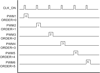
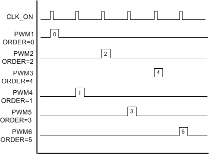
- ORDER: Controls the order in which phases are fired with respect to each other. Figure 7-15 and Figure 7-16 illustrate the effect of different ordering assignments. Reconfigure the phase ordering to ensure adjacent phases do not interfere with each other due to layout related coupling issues. If dynamic phase shedding is used, phases add or drop according to their assigned ORDER value.
 Figure 7-15 0-1-2-3-4-5 fire order (6 phase example)
 Figure 7-16 0-2-4-1-3-5 fire order (6 phase example)
Observe the following rules when updating the phase configuration settings. The Fusion Digital Power Designer GUI enforces these rules, but the controller itself does not:
- Channel A may be assigned up to 7 phases. Channel B may be assigned up to 3 phases.
- The ORDER assignments within a channel must be continuous, and start at 0. Do not skip phase order assignments.
- The PHASE assignments within a channel must be continuous, start at 0 counting upward from APWM1 for channel A and downward from BPWM1 for channel B.
Example: 3+2 phase configuration with non-standard fire order
- Disable power conversion, as specified per ON_OFF_CONFIG.
- Write the PHASE_CONFIG command as shown below.
- Issue STORE_DEFAULT_ALL to save the current settings into NVM as default values for the next power-on.
Table 7-7 Example settings: 3+2
| Physical Phase | Enable | Page | Phase | Order |
|---|---|---|---|---|
| Pins 12, 27 (APWM1) | 1 | 0 | 0 | 0 |
| Pins 11, 28 (APWM2) | 1 | 0 | 1 | 2 |
| Pins 10, 29 (APWM3) | 1 | 0 | 2 | 1 |
| Pins 9, 30 (APWM4) | 0 | x | x | x |
| Pins 8, 31 (APWM5/BPWM3) | 0 | x | x | x |
| Pins 7, 32 (APWM6/BPWM2) | 1 | 1 | 1 | 1 |
| Pins 6, 33 (APWM7/BPWM1) | 1 | 1 | 0 | 0 |
| Pins 5, 34 (NC) | 0 | x | x | x |
| Pins 4, 35 (NC) | 0 | x | x | x |
| Pins 3, 36 (NC) | 0 | x | x | x |
| Pins 2, 37 (NC) | 0 | x | x | x |
| Pins 1, 37 (NC) | 0 | x | x | x |