ZHCSN24A August 2019 – May 2021 TPS53676
PRODUCTION DATA
- 1 特性
- 2 应用
- 3 说明
- 4 Revision History
- 5 Pin Configuration and Functions
-
6 Specifications
- 6.1 Absolute Maximum Ratings
- 6.2 Recommended Operating Conditions
- 6.3 ESD Ratings
- 6.4
Electrical Specifications
- 6.4.1 Thermal Information
- 6.4.2 Supply
- 6.4.3 DAC and Voltage Feedback
- 6.4.4 Control Loop Parameters
- 6.4.5 Dynamic VID (DVID) Tuning
- 6.4.6 Undershoot Reduction (USR) and Overshoot Reduciton (OSR)
- 6.4.7 Dynamic Phase Shedding (DPS)
- 6.4.8 Turbo Mode and Thermal Balance Management (TBM)
- 6.4.9 Overcurrent Limit (OCL)
- 6.4.10 Telemetry
- 6.4.11 Phase-Locked Loop and Closed-Loop Frequency Control
- 6.4.12 Logic Interface
- 6.4.13 Current Sensing and Current Sharing
- 6.4.14 Pin Detection Thresholds
- 6.4.15 ADDR Pinstrap Decoding
- 6.4.16 BOOT_CHA Pinstrap Decoding
- 6.4.17 Timing Specifications
- 6.4.18 Faults and Converter Protection
- 6.4.19 PMBus/AVS Interfaces
-
7 Detailed Description
- 7.1 Overview
- 7.2 Functional Block Diagram
- 7.3 Power-up and initialization
- 7.4
Pin connections and bevahior
- 7.4.1 Supplies: VCC and VREF
- 7.4.2 Differential remote sensing and output voltage scaling: AVSP/AVSN, BVSP/BVSN
- 7.4.3 Input current sensing: VIN_CSNIN and CSPIN
- 7.4.4 Pin-strap detection and PIN_DETECT_OVERRIDE
- 7.4.5 Enable and disable: AVR_EN and BVR_EN
- 7.4.6 System feedback: AVR_RDY and BVR_RDY
- 7.4.7 Catastrophic fault alert: VR_FAULT#
- 7.4.8 Output voltage reset: RESET#
- 7.4.9 Synchronization: SYNC
- 7.4.10 Smart power stage connections: PWM, CSP and TSEN
- 7.4.11 PMBus pins: SMB_DIO, SMB_CLK, and SMB_ALERT#
- 7.4.12 AVSBus: AVS_CLK, AVS_MDATA, AVS_SDATA, and AVS_VDDIO
- 7.5 Advanced power management functions
- 7.6
Control Loop Theory of Operation
- 7.6.1 Adaptive voltage positioning and DC load line (droop)
- 7.6.2 DCAP+ conceptual overview
- 7.6.3 Off-time control: loop compensation and transient tuning
- 7.6.4 On-time control: adaptive ton and autobalance current sharing
- 7.6.5 Load transient response
- 7.6.6 Forced minimum on-time, minimum off-time and leading-edge blanking time
- 7.6.7 Nonlinear: undershoot reduction (USR), overshoot reduction (OSR) and dynamic integration
- 7.7
Power supply fault protection
- 7.7.1 Host notification and status reporting
- 7.7.2 Fault type and response definitions
- 7.7.3 Fault behavior summary
- 7.7.4
Detailed fault descriptions
- 7.7.4.1 Overvoltage fault (OVF) and warning (OVW)
- 7.7.4.2 Undervoltage fault (UVF) and warning (UVW)
- 7.7.4.3 Maximum turn-on time exceeded (TON_MAX)
- 7.7.4.4 Output commanded out-of-bounds (VOUT_MIN_MAX)
- 7.7.4.5 Overcurrent fault (OCF), warning (OCW), and per-phase overcurrent limit (OCL)
- 7.7.4.6 Current share warning (ISHARE)
- 7.7.4.7 Overtemperature fault protection (OTF) and warning (OTW)
- 7.7.4.8 Powerstage fault (TAO_HIGH) and powerstage not ready (TAO_LOW)
- 7.7.4.9 Input overvoltage fault (VIN_OVF) and warning (VIN_OVW)
- 7.7.4.10 Input undervoltage fault (VIN_UVF), warning (VIN_UVW) and turn-on voltage (VIN_ON)
- 7.7.4.11 Input overcurrent fault (IIN_OCF) and warning (IIN_OCW)
- 7.7.4.12 Input overpower warning (PIN_OPW)
- 7.7.4.13 PMBus command, memory and logic errors (CML)
- 7.8
Programming
- 7.8.1
PMBus Interface
- 7.8.1.1 PMBus transaction types
- 7.8.1.2 PMBus data formats
- 7.8.1.3 Raw non-volatile memory programming
- 93
- 7.8.1.4
PMBus Command Descriptions
- 7.8.1.4.1 (00h) PAGE
- 7.8.1.4.2 (01h) OPERATION
- 7.8.1.4.3 (02h) ON_OFF_CONFIG
- 7.8.1.4.4 (03h) CLEAR_FAULTS
- 7.8.1.4.5 (04h) PHASE
- 7.8.1.4.6 (05h) PAGE_PLUS_WRITE
- 7.8.1.4.7 (06h) PAGE_PLUS_READ
- 7.8.1.4.8 (10h) WRITE_PROTECT
- 7.8.1.4.9 (15h) STORE_USER_ALL
- 7.8.1.4.10 (16h) RESTORE_USER_ALL
- 7.8.1.4.11 (19h) CAPABILITY
- 7.8.1.4.12 (1Bh) SMBALERT_MASK_WORD
- 7.8.1.4.13 (1Bh) SMBALERT_MASK_VOUT
- 7.8.1.4.14 (1Bh) SMBALERT_MASK_IOUT
- 7.8.1.4.15 (1Bh) SMBALERT_MASK_INPUT
- 7.8.1.4.16 (1Bh) SMBALERT_MASK_TEMPERATURE
- 7.8.1.4.17 (1Bh) SMBALERT_MASK_CML
- 7.8.1.4.18 (1Bh) SMBALERT_MASK_MFR
- 7.8.1.4.19 (20h) VOUT_MODE
- 7.8.1.4.20 (21h) VOUT_COMMAND
- 7.8.1.4.21 (22h) VOUT_TRIM
- 7.8.1.4.22 (24h) VOUT_MAX
- 7.8.1.4.23 (25h) VOUT_MARGIN_HIGH
- 7.8.1.4.24 (26h) VOUT_MARGIN_LOW
- 7.8.1.4.25 (27h) VOUT_TRANSITION_RATE
- 7.8.1.4.26 (28h) VOUT_DROOP
- 7.8.1.4.27 (29h) VOUT_SCALE_LOOP
- 7.8.1.4.28 (2Bh) VOUT_MIN
- 7.8.1.4.29 (33h) FREQUENCY_SWITCH
- 7.8.1.4.30 (34h) POWER_MODE
- 7.8.1.4.31 (35h) VIN_ON
- 7.8.1.4.32 (38h) IOUT_CAL_GAIN
- 7.8.1.4.33 (39h) IOUT_CAL_OFFSET
- 7.8.1.4.34 (40h) VOUT_OV_FAULT_LIMIT
- 7.8.1.4.35 (41h) VOUT_OV_FAULT_RESPONSE
- 7.8.1.4.36 (42h) VOUT_OV_WARN_LIMIT
- 7.8.1.4.37 (43h) VOUT_UV_WARN_LIMIT
- 7.8.1.4.38 (44h) VOUT_UV_FAULT_LIMIT
- 7.8.1.4.39 (45h) VOUT_UV_FAULT_RESPONSE
- 7.8.1.4.40 (46h) IOUT_OC_FAULT_LIMIT
- 7.8.1.4.41 (47h) IOUT_OC_FAULT_RESPONSE
- 7.8.1.4.42 (4Ah) IOUT_OC_WARN_LIMIT
- 7.8.1.4.43 (4Fh) OT_FAULT_LIMIT
- 7.8.1.4.44 (50h) OT_FAULT_RESPONSE
- 7.8.1.4.45 (51h) OT_WARN_LIMIT
- 7.8.1.4.46 (55h) VIN_OV_FAULT_LIMIT
- 7.8.1.4.47 (56h) VIN_OV_FAULT_RESPONSE
- 7.8.1.4.48 (57h) VIN_OV_WARN_LIMIT
- 7.8.1.4.49 (58h) VIN_UV_WARN_LIMIT
- 7.8.1.4.50 (59h) VIN_UV_FAULT_LIMIT
- 7.8.1.4.51 (5Ah) VIN_UV_FAULT_RESPONSE
- 7.8.1.4.52 (5Bh) IIN_OC_FAULT_LIMIT
- 7.8.1.4.53 (5Ch) IIN_OC_FAULT_RESPONSE
- 7.8.1.4.54 (5Dh) IIN_OC_WARN_LIMIT
- 7.8.1.4.55 (60h) TON_DELAY
- 7.8.1.4.56 (61h) TON_RISE
- 7.8.1.4.57 (62h) TON_MAX_FAULT_LIMIT
- 7.8.1.4.58 (63h) TON_MAX_FAULT_RESPONSE
- 7.8.1.4.59 (64h) TOFF_DELAY
- 7.8.1.4.60 (65h) TOFF_FALL
- 7.8.1.4.61 (6Bh) PIN_OP_WARN_LIMIT
- 7.8.1.4.62 (78h) STATUS_BYTE
- 7.8.1.4.63 (79h) STATUS_WORD
- 7.8.1.4.64 (7Ah) STATUS_VOUT
- 7.8.1.4.65 (7Bh) STATUS_IOUT
- 7.8.1.4.66 (7Ch) STATUS_INPUT
- 7.8.1.4.67 (7Dh) STATUS_TEMPERATURE
- 7.8.1.4.68 (7Eh) STATUS_CML
- 7.8.1.4.69 (80h) STATUS_MFR_SPECIFIC
- 7.8.1.4.70 (88h) READ_VIN
- 7.8.1.4.71 (89h) READ_IIN
- 7.8.1.4.72 (8Bh) READ_VOUT
- 7.8.1.4.73 (8Ch) READ_IOUT
- 7.8.1.4.74 (8Dh) READ_TEMPERATURE_1
- 7.8.1.4.75 (96h) READ_POUT
- 7.8.1.4.76 (97h) READ_PIN
- 7.8.1.4.77 (98h) PMBUS_REVISION
- 7.8.1.4.78 (99h) MFR_ID
- 7.8.1.4.79 (9Ah) MFR_MODEL
- 7.8.1.4.80 (9Bh) MFR_REVISION
- 7.8.1.4.81 (9Dh) MFR_DATE
- 7.8.1.4.82 (ADh) IC_DEVICE_ID
- 7.8.1.4.83 (AEh) IC_DEVICE_REV
- 7.8.1.4.84 (B1h) USER_DATA_01 (COMPENSATION_CONFIG)
- 7.8.1.4.85 (B2h) USER_DATA_02 (NONLINEAR_CONFIG)
- 7.8.1.4.86 (B3h) USER_DATA_03 (PHASE_CONFIG)
- 7.8.1.4.87 (B4h) USER_DATA_04 (DVID_CONFIG)
- 7.8.1.4.88 (B7h) USER_DATA_07 (PHASE_SHED_CONFIG)
- 7.8.1.4.89 (B8h) USER_DATA_08 (AVSBUS_CONFIG)
- 7.8.1.4.90 (BAh) USER_DATA_10 (ISHARE_CONFIG)
- 7.8.1.4.91 (BBh) USER_DATA_11 (MFR_PROTECTION_CONFIG)
- 7.8.1.4.92 (BDh) USER_DATA_13 (MFR_CALIBRATION_CONFIG)
- 7.8.1.4.93 (CDh) MFR_SPECIFIC_CD (MULTIFUNCTION_PIN_CONFIG_1)
- 7.8.1.4.94 (CEh) MFR_SPECIFIC_CD (MULTIFUNCTION_PIN_CONFIG_2)
- 7.8.1.4.95 (CFh) SMBALERT_MASK_EXTENDED
- 7.8.1.4.96 (D1h) READ_VOUT_MIN_MAX
- 7.8.1.4.97 (D2h) READ_IOUT_MIN_MAX
- 7.8.1.4.98 (D3h) READ_TEMPERATURE_MIN_MAX)
- 7.8.1.4.99 (D4h) READ_MFR_VOUT
- 7.8.1.4.100 (D5h) READ_VIN_MIN_MAX
- 7.8.1.4.101 (D6h) READ_IIN_MIN_MAX
- 7.8.1.4.102 (D7h) READ_PIN_MIN_MAX
- 7.8.1.4.103 (D8h) READ_POUT_MIN_MAX
- 7.8.1.4.104 (DAh) READ_ALL
- 7.8.1.4.105 (DBh) STATUS_ALL
- 7.8.1.4.106 (DCh) STATUS_PHASES
- 7.8.1.4.107 (DDh) STATUS_EXTENDED
- 7.8.1.4.108 (E0h) AVSBUS_LOG
- 7.8.1.4.109 (E3h) MFR_SPECIFIC_E3 (VR_FAULT_CONFIG)
- 7.8.1.4.110 (E4h) SYNC_CONFIG
- 7.8.1.4.111 (EDh) MFR_SPECIFIC_ED (MISC_OPTIONS)
- 7.8.1.4.112 (EEh) MFR_SPECIFIC_EE (PIN_DETECT_OVERRIDE)
- 7.8.1.4.113 (EFh) MFR_SPECIFIC_EF (SLAVE_ADDRESS)
- 7.8.1.4.114 (F0h) MFR_SPECIFIC_F0 (NVM_CHECKSUM)
- 7.8.1.4.115 (F5h) MFR_SPECIFIC_F5 (USER_NVM_INDEX)
- 7.8.1.4.116 (F6h) MFR_SPECIFIC_F6 (USER_NVM_EXECUTE)
- 7.8.1.4.117 (FAh) NVM_LOCK
- 7.8.1.4.118 (FBh) MFR_SPECIFIC_WRITE_PROTECT
- 7.8.2 AVSBus Interface
- 7.8.1
PMBus Interface
- 8 Applications and Implementation
- 9 Power Supply Recommendations
- 10Layout
- 11Device and Documentation Support
- 12Mechanical, Packaging, and Orderable Information
10 Layout
Proper layout techniques are critical to power supply performance. The recommendations given in this document are meant to minimize risk and give the highest possibility of first pass success. Other layout designs are possible but may carry higher risk of performance issues. Contact your TI local field/sales representative for in-depth guidance and layout reviews.
The driverless controller architecture makes it easy to separate noisy driver interface lines from sensitive controller signals. Because the power stage is external to the device, all gate drive and switch node traces must be local to the inductor and power stages.
Controller Layout Guidelines
- Keep minimum 800 mil distance between the controller and the closest power stage
- Ensure the controller and all power stages must share a common ground plane
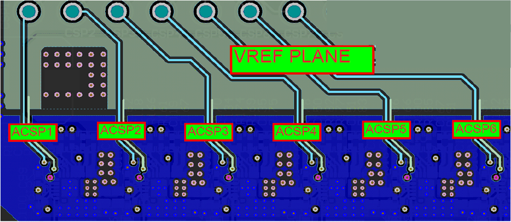
- Route CSPx /VREF differentially from controller to IOUT/REFIN pin of each power stages on a quiet inner layer. Alternately, create a small VREF copper plane between controller and power stages, and embed the CSPx traces inside VREF plane.
- PWMx must be routed on a different quiet inner layer and not on the same layer next to CSPx/VREF differential pairs.
Power stage layout guidelines
- Use the recommended land and via pattern for power stage footprint
- Make layer 2 on the PCB stack a solid ground plane
- Maximize the phase pitch between adjacent phases whenever possible to prevent any cross-coupling noise between devices (9 mm or higher is preferred)
- In cases where the phase pitch is tighter, adjust the controller phase firing order to minimize noise coupling between devices.
- The input voltage bypass capacitors require a minimum two vias per pad(for both Vin and GND)
- Place additional GND vias along the sides of device as space allows
- For multi-phase systems, ensure that the GND pour connects all phases.
- Connect the VOS pin feedback point to the inner edge of the inductor output pad.
- Place VDD and PVDD bypass capacitors directly next to pins on the same layer of the device.
Layout example
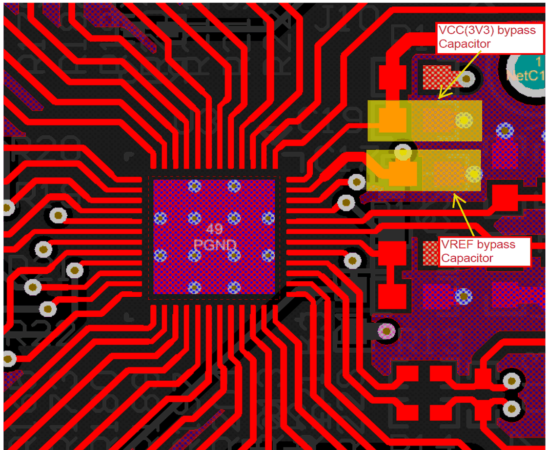
 Figure 10-1 Controller layout
example
 Figure 10-2 CSP signal routing
example
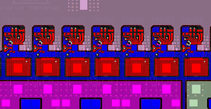
 Figure 10-3 Power stage placement
example