ZHCSJK9H June 2001 – October 2015 TPS54610
PRODUCTION DATA.
- 1 特性
- 2 应用
- 3 说明
- 4 修订历史记录
- 5 Device Comparison Table
- 6 Pin Configuration and Functions
- 7 Specifications
-
8 Detailed Description
- 8.1 Overview
- 8.2 Functional Block Diagram
- 8.3
Feature Description
- 8.3.1 Undervoltage Lockout (UVLO)
- 8.3.2 Slow Start/Enable (SS/ENA)
- 8.3.3 VBIAS Regulator (VBIAS)
- 8.3.4 Voltage Reference
- 8.3.5 Oscillator and PWM Ramp
- 8.3.6 Error Amplifier
- 8.3.7 PWM Control
- 8.3.8 Dead-Time Control and MOSFET Drivers
- 8.3.9 Overcurrent Protection
- 8.3.10 Thermal Shutdown
- 8.3.11 Power-Good (PWRGD)
- 8.4 Device Functional Modes
- 9 Application and Implementation
- 10Power Supply Recommendations
- 11Layout
- 12器件和文档支持
- 13机械、封装和可订购信息
封装选项
机械数据 (封装 | 引脚)
- PWP|28
散热焊盘机械数据 (封装 | 引脚)
- PWP|28
订购信息
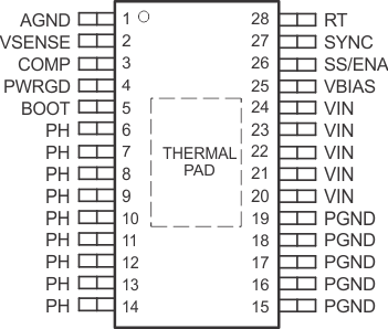
6 Pin Configuration and Functions
PWP Package
28-Pin HTSSOP With Exposed Thermal Pad
Top View

Pin Functions
| PIN | TYPE(1) | DESCRIPTION | |
|---|---|---|---|
| NAME | NO. | ||
| AGND | 1 | G | Analog ground. Return for compensation network/output divider, slow-start capacitor, VBIAS capacitor, RT resistor and SYNC pin. Connect PowerPAD™ to AGND. |
| BOOT | 5 | S | Bootstrap output. 0.022-μF to 0.1-μF low-ESR capacitor connected from BOOT to PH generates floating drive for the high-side FET driver. |
| COMP | 3 | Error amplifier output. Connect frequency compensation network from COMP to VSENSE | |
| PGND | 15-19 | G | Power ground. High current return for the low-side driver and power MOSFET. Connect PGND with large copper areas to the input and output supply returns, and negative pins of the input and output capacitors. A single point connection to AGND is recommended. |
| PH | 6-14 | O | Phase output. Junction of the internal high-side and low-side power MOSFETs, and output inductor. |
| PWRGD | 4 | O | Power good open drain output. High when VSENSE ≥ 90% Vref, otherwise PWRGD is low. Note that output is low when SS/ENA is low or the internal shutdown signal is active. |
| RT | 28 | I | Frequency setting resistor input. Connect a resistor from RT to AGND to set the switching frequency. When using the SYNC pin, set the RT value for a frequency at or slightly lower than the external oscillator frequency. |
| SS/ENA | 26 | I/O | Slow-start/enable input/output. Dual function pin which provides logic input to enable/disable device operation and capacitor input to externally set the start-up time. |
| SYNC | 27 | I/O | Synchronization input. Dual function pin which provides logic input to synchronize to an external oscillator or pin select between two internally set switching frequencies. When used to synchronize to an external signal, a resistor must be connected to the RT pin. |
| VBIAS | 25 | S | Internal bias regulator output. Supplies regulated voltage to internal circuitry. Bypass VBIAS pin to AGND pin with a high quality, low-ESR 0.1-μF to 1.0-μF ceramic capacitor. |
| VIN | 20-24 | I | Input supply for the power MOSFET switches and internal bias regulator. Bypass VIN pins to PGND pins close to device package with a high quality, low-ESR 10-μF ceramic capacitor. |
| VSENSE | 2 | I | Error amplifier inverting input. Connect to output voltage through compensation network/output divider. |
(1) I = Input, O = Output, S = Supply, G = Ground Return