ZHCSKY4B November 2018 – December 2020 TPS55288
PRODUCTION DATA
- 1 特性
- 2 应用
- 3 说明
- 4 Revision History
- 5 Pin Configuration and Functions
- 6 Specifications
-
7 Detailed Description
- 7.1 Overview
- 7.2 Functional Block Diagram
- 7.3
Feature Description
- 7.3.1 VCC Power Supply
- 7.3.2 Operation Mode Setting
- 7.3.3 Input Undervoltage Lockout
- 7.3.4 Enable and Programmable UVLO
- 7.3.5 Soft Start
- 7.3.6 Shutdown and Load Discharge
- 7.3.7 Switching Frequency
- 7.3.8 Switching Frequency Dithering
- 7.3.9 Inductor Current Limit
- 7.3.10 Internal Charge Path
- 7.3.11 Output Voltage Setting
- 7.3.12 Output Current Monitoring and Cable Voltage Droop Compensation
- 7.3.13 Integrated Gate Drivers
- 7.3.14 Output Current Limit
- 7.3.15 Overvoltage Protection
- 7.3.16 Output Short Circuit Protection
- 7.3.17 Thermal Shutdown
- 7.4 Device Functional Modes
- 7.5 I2C Serial Interface
- 7.6
Register Maps
- 7.6.1 REF Register (Address = 0h, 1h) [reset = 11010010h, 00000000h]
- 7.6.2 IOUT_LIMIT Register (Address = 2h) [reset = 11100100h]
- 7.6.3 VOUT_SR Register (Address = 3h) [reset = 00000001h]
- 7.6.4 VOUT_FS Register (Address = 4h) [reset = 00000011h]
- 7.6.5 CDC Register (Address = 5h) [reset = 11100000h]
- 7.6.6 MODE Register (Address = 6h) [reset = 00100000h]
- 7.6.7 STATUS Register (Address = 7h) [reset = 00000011h]
- 7.6.8 Register Summary
- 8 Application and Implementation
- 9 Power Supply Recommendations
- 10Layout
- 11Device and Documentation Support
- 12Mechanical, Packaging, and Orderable Information
3 说明
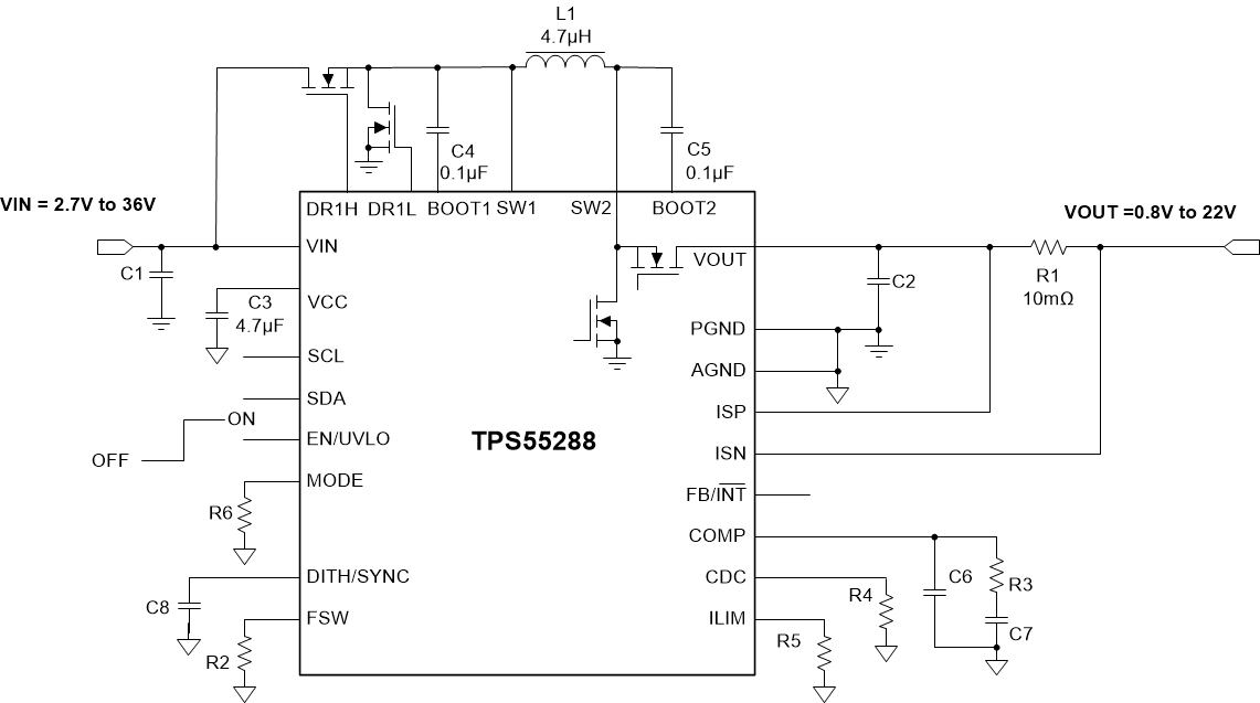
TPS55288 是一款同步四开关降压/升压转换器,能够将输出电压稳定在等于、高于或低于输入电压的某一电压值上。TPS55288 在 2.7V 至 36V 的宽输入电压范围内工作,可输出 0.8V 至 22V 电压以支持各种不同的应用。
TPS55288 集成了两个 16A MOSFET,其中的升压桥臂可实现解决方案尺寸和效率间的平衡。通过 I2C 接口对输出电压和输出电流限制进行编程,TPS55288 完全符合 USB PD 规范。TPS55288 能够通过 12V 输入电压提供 100W 的功率。
TPS55288 采用平均电流模式控制方案。开关频率可通过外部电阻在 200 kHz 至 2.2 MHz 之间进行编程,并且可与外部时钟同步。TPS55288 还提供展频选项,从而更大限度地减少峰值 EMI。
TPS55288 提供输出过压保护、平均电感器电流限制、逐周期峰值电流限制和输出短路保护。TPS55288 还通过可选输出电流限制和断续模式保护,在持续过载情况下确保安全运行。
TPS55288 可在高开关频率下使用小型电感器和小型电容器。此器件采用 4.0mm × 3.5mm QFN 封装。
器件信息
| 器件型号 | 封装(1) | 封装尺寸 |
|---|---|---|
| TPS55288 | VQFN-HR | 4.00mm × 3.50mm |
(1) 如需了解所有可用封装,请参阅数据表末尾的可订购米6体育平台手机版_好二三四附录。
 典型应用电路