ZHCSJL9B April   2019  – April 2019 TPS566235

PRODUCTION DATA.  

  1. 特性
  2. 应用
  3. 说明
    1.     Device Images
      1.      典型应用
      2.      效率与输出电流 Eco-mode
  4. 修订历史记录
  5. Pin Configuration and Functions
    1.     Pin Functions
  6. Specifications
    1. 6.1 Absolute Maximum Ratings
    2. 6.2 ESD Ratings
    3. 6.3 Recommended Operating Conditions
    4. 6.4 Thermal Information
    5. 6.5 Electrical Characteristics
    6. 6.6 Typical Characteristics
  7. Detailed Description
    1. 7.1 Overview
    2. 7.2 Functional Block Diagram
    3. 7.3 Feature Description
      1. 7.3.1 PWM Operation and D-CAP3 Control
      2. 7.3.2 Power Good
      3. 7.3.3 Soft Start and Pre-Biased Soft Start
      4. 7.3.4 Over current Protection and Undervoltage Protection
      5. 7.3.5 Over Voltage Protection
      6. 7.3.6 UVLO Protection
      7. 7.3.7 Thermal Shutdown
    4. 7.4 Device Functional Modes
      1. 7.4.1 Light Load Operation
      2. 7.4.2 MODE Pin Configuration
      3. 7.4.3 Advanced Eco-Mode Control
      4. 7.4.4 Out-Of-Audio Mode
      5. 7.4.5 Force CCM Mode
      6. 7.4.6 Standby Operation
  8. Application and Implementation
    1. 8.1 Application Information
    2. 8.2 Typical Application
      1. 8.2.1 Design Requirements
      2. 8.2.2 Detailed Design Procedure
        1. 8.2.2.1 Custom Design With WEBENCH® Tools
        2. 8.2.2.2 Inductor Selection
        3. 8.2.2.3 Output Capacitor Selection
        4. 8.2.2.4 Input Capacitor Selection
      3. 8.2.3 Application Curves
  9. Power Supply Recommendations
  10. 10Layout
    1. 10.1 Layout Guidelines
    2. 10.2 Layout Example
  11. 11器件和文档支持
    1. 11.1 器件支持
      1. 11.1.1 第三方米6体育平台手机版_好二三四免责声明
      2. 11.1.2 开发支持
        1. 11.1.2.1 使用 WEBENCH® 工具创建定制设计
    2. 11.2 接收文档更新通知
    3. 11.3 社区资源
    4. 11.4 商标
    5. 11.5 静电放电警告
    6. 11.6 术语表
  12. 12机械、封装和可订购信息

封装选项

机械数据 (封装 | 引脚)
散热焊盘机械数据 (封装 | 引脚)
订购信息

Pin Configuration and Functions

RJN Package
13-Pin VQFN
Top View
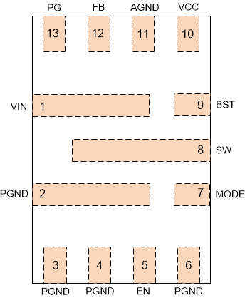
TPS566235 pinout-01-rgy-pkg-slvsew1.gif

Pin Functions

PIN I/O DESCRIPTION
NAME NO.
VIN 1 P Input voltage supply pin for the control circuitry. Connect the input decoupling capacitors between VIN and PGND.
PGND 2,3,4,6 G Power GND terminal for the controller circuit and the internal circuitry.
EN 5 I Enable pin of Buck converter. EN pin is a digital input pin, decides turn on/off Buck converter. Internal pull down current to disable converter if leave this pin open.
MODE 7 I Eco-Mode™/OOA/FCCM Mode selection pin with external 1% resistor or connecting to VCC.
SW 8 O Switching node connection to the output inductor and bootstrap capacitor.
BST 9 I Supply input for the gate drive voltage of the high-side MOSFET. Connect the bootstrap capacitor between BST and SW, 0.1 uF is recommended.
VCC 10 P Internal LDO output for control and driver. Decouple with a minimum 1 μF ceramic capacitor as close to VCC as possible.
AGND 11 G Ground of internal analog circuitry. Connect AGND to GND plane with a short trace.
FB 12 I Feedback sensing pin for Buck output voltage. Connect this pin to the resistor divider between output voltage and AGND.
PG 13 O Open drain power good indicator. It is asserted low if output voltage is out of PG threshold, over voltage or if the device is under thermal shutdown, EN shutdown or during soft start.