SLVS427D JUNE 2002 – May 2015 TPS61120 , TPS61121 , TPS61122
PRODUCTION DATA.
- 1 Features
- 2 Applications
- 3 Description
- 4 Revision History
- 5 Device Options
- 6 Pin Configuration and Functions
- 7 Specifications
- 8 Parameter Measurement Information
- 9 Detailed Description
-
10Application and Implementation
- 10.1 Application Information
- 10.2
Typical Applications
- 10.2.1 Solution for Maximum Output Power
- 10.2.2 Low Profile Solution, Maximum Height 1.8 mm
- 10.2.3 Dual Power Supply With Auxiliary Positive Output Voltage
- 10.2.4 Dual Power Supply With Auxiliary Negative Output Voltage
- 10.2.5 Single Output Using LDO as Filter
- 10.2.6 Dual Input Power Supply Solution
- 11Power Supply Recommendations
- 12Layout
- 13Device and Documentation Support
- 14Mechanical, Packaging, and Orderable Information
封装选项
请参考 PDF 数据表获取器件具体的封装图。
机械数据 (封装 | 引脚)
- PW|16
- RSA|16
散热焊盘机械数据 (封装 | 引脚)
- RSA|16
订购信息
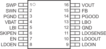
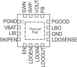
6 Pin Configuration and Functions
PW Package
16-Pin TSSOP
Top View

RSA Package
16-Pin VQFN With Thermal Pad
Top View

Pin Functions
| PIN | I/O | DESCRIPTION | ||
|---|---|---|---|---|
| NAME | NO. | |||
| TSSOP | VQFN | |||
| EN | 7 | 5 | I | DC-DC-enable input. (1: VBAT enabled, 0: GND disabled) |
| FB | 15 | 13 | I | DC-DC voltage feedback of adjustable versions |
| GND | 12 | 10 | I/O | Control/logic ground |
| LBI | 5 | 3 | I | Low battery comparator input (comparator enabled with EN) |
| LBO | 13 | 11 | O | Low battery comparator output (open drain) |
| LDOEN | 8 | 6 | I | LDO-enable input (1: LDOIN enabled, 0: GND disabled) |
| LDOOUT | 10 | 8 | O | LDO output |
| LDOIN | 9 | 7 | I | LDO input |
| LDOSENSE | 11 | 9 | I | LDO feedback for voltage adjustment, must be connected to LDOOUT at fixed output voltage versions |
| SWP | 1 | 15 | I | DC-DC rectifying switch input |
| PGND | 3 | 1 | I/O | Power ground |
| PGOOD | 14 | 12 | O | DC-DC output power good (1: good, 0 : failure) (open drain) |
| SKIPEN | 6 | 4 | I | Enable/disable power save mode (1: VBAT enabled, 0: GND disabled) |
| SWN | 2 | 16 | I | DC-DC switch input |
| VBAT | 4 | 2 | I | Supply pin |
| VOUT | 16 | 14 | O | DC-DC output |