ZHCSMN1A December 2015 – January 2021 TPS62097
PRODUCTION DATA
- 1 特性
- 2 应用
- 3 说明
- 4 Revision History
- 5 Device Options
- 6 Pin Configuration and Functions
- 7 Specifications
- 8 Detailed Description
- 9 Application and Implementation
- 10Power Supply Recommendations
- 11Layout
- 12Device and Documentation Support
- 13Mechanical, Packaging, and Orderable Information
9.2.2.3 Inductor Selection
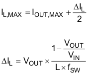
The main parameters for the inductor selection are the inductor value and the saturation current. To calculate the maximum inductor current under static load conditions, Equation 5 is given.
Equation 5. 

Where:
IOUT,MAX = Maximum output current
ΔIL = Inductor current ripple
fSW = Switching frequency
L = Inductor value
TI recommends to choose the saturation current for the inductor 20% to 30% higher than the IL,MAX, out of Equation 5. A higher inductor value is also useful to lower ripple current but increases the transient response time as well. The following inductors are recommended to be used in designs.
Table 9-4 List of Recommended Inductors
| INDUCTANCE [µH] | CURRENT RATING [A] | DIMENSIONS L x W x H [mm3] | DC RESISTANCE [mΩ TYP] | PART NUMBER(1) |
|---|---|---|---|---|
| 1 | 5.4 | 4.0x4.0x2.0 | 11 | COILCRAFT XFL4020-102ME |
| 1 | 5.3 | 2.5x2.0x1.2 | 33 | TOKO DFE252012F-1R0M |
| 1 | 3.4 | 2.0x1.2x1.0 | 62 | TOKO DFE201210S-1R0M |
| 1 | 5.1 | 3.0x3.0x1.2 | 43 | TAIYO YUDEN MDMK3030T1R0MM |
| 1 | 4.2 | 2.5x2.0x1.2 | 43 | CYNTEC SDEM25201B-1R0MS-79 |
| 1 | 2.6 | 2.5x2.0x1.2 | 48 | Murata LQH2HPN1R0NJR |
| 1 | 6.6 | 3.0x3.0x1.2 | 42 | Wurth Electronics 74438334010 |
(1) See Third-Party Products Disclaimer