ZHCSCQ4B August   2014  – May 2017 TPS62180 , TPS62182

PRODUCTION DATA.  

  1. 特性
  2. 应用
  3. 说明
  4. 修订历史记录
  5. Device Comparison Table
  6. Pin Configuration and Functions
  7. Specifications
    1. 7.1 Absolute Maximum Ratings
    2. 7.2 ESD Ratings
    3. 7.3 Recommended Operating Conditions
    4. 7.4 Thermal Information
    5. 7.5 Electrical Characteristics
    6. 7.6 Typical Characteristics
  8. Detailed Description
    1. 8.1 Overview
    2. 8.2 Functional Block Diagram
    3. 8.3 Feature Description
      1. 8.3.1 Enable / Shutdown (EN)
      2. 8.3.2 Soft Start / Tracking (SS/TR)
      3. 8.3.3 Power Good (PG)
      4. 8.3.4 Undervoltage Lockout (UVLO)
      5. 8.3.5 Thermal Shutdown
    4. 8.4 Device Functional Modes
      1. 8.4.1 Pulse Width Modulation (PWM) Operation
      2. 8.4.2 Power Save Mode (PSM) Operation
      3. 8.4.3 Minimum Duty Cycle and 100% Mode Operation
      4. 8.4.4 Automatic Efficiency Enhancement (AEE)
      5. 8.4.5 Phase-Shifted Operation
      6. 8.4.6 Current Limit, Current Balancing, and Short Circuit Protection
      7. 8.4.7 Tracking
      8. 8.4.8 Operation with Fixed VOUT
  9. Application and Implementation
    1. 9.1 Application Information
    2. 9.2 Typical Applications
      1. 9.2.1 Typical TPS62180 Application
        1. 9.2.1.1 Design Requirements
        2. 9.2.1.2 Detailed Design Procedure
          1. 9.2.1.2.1 Custom Design With WEBENCH® Tools
          2. 9.2.1.2.2 Programming the Output Voltage
          3. 9.2.1.2.3 Output Filter Selection
          4. 9.2.1.2.4 Inductor Selection
          5. 9.2.1.2.5 Output Capacitor Selection
          6. 9.2.1.2.6 Input Capacitor Selection
          7. 9.2.1.2.7 Soft Start Capacitor Selection
        3. 9.2.1.3 Application Performance Curves
      2. 9.2.2 TPS62180 Low Profile Solution
        1. 9.2.2.1 Design Requirements
        2. 9.2.2.2 Detailed Design Procedure
          1. 9.2.2.2.1 Inductor
          2. 9.2.2.2.2 Input and Output Capacitors
          3. 9.2.2.2.3 Soft Start Capacitor
          4. 9.2.2.2.4 Using the Accurate EN Threshold
        3. 9.2.2.3 Application Performance Curves
    3. 9.3 TPS62180 Output Voltage Application Examples
      1. 9.3.1 Application Schematic Examples
      2. 9.3.2 Design Requirements
      3. 9.3.3 External Component Selection
  10. 10Power Supply Recommendations
  11. 11Layout
    1. 11.1 Layout Guidelines
      1. 11.1.1 PCB Layout
    2. 11.2 Layout Example
  12. 12器件和文档支持
    1. 12.1 器件支持
      1. 12.1.1 Third-Party Products Disclaimer
    2. 12.2 相关链接
    3. 12.3 商标
    4. 12.4 静电放电警告
    5. 12.5 Glossary
  13. 13机械、封装和可订购信息

封装选项

机械数据 (封装 | 引脚)
散热焊盘机械数据 (封装 | 引脚)
订购信息

特性

  • 双相平衡峰值电流模式
  • 输入电压范围:4V 至 15V
  • 输出电压范围:0.9V 至 6V
  • 输出电流高达 6A
  • 典型静态电流为 28µA
  • 输出电压精度达 ±1%(脉宽调制 (PWM) 模式)
  • 自动效率提高 (AEE™)
  • 相移操作
  • 自动节能模式
  • 可调软启动
  • 电源正常输出
  • 欠压闭锁
  • HICCUP 过流保护
  • TPS62184 引脚对引脚兼容
  • 过热保护
  • NanoFree™2.10mm x 3.10mm 芯片尺寸球状引脚栅格阵列 (DSBGA) 封装
  • 结合使用 TPS62180 和 WEBENCH® 电源设计器创建定制设计方案

应用

  • 薄型负载点 (POL) 电源
  • 窄 VDC (NVDC) 供电系统
  • 两/三节锂离子电池
  • 超便携式/嵌入式/平板电脑
  • 计算网络解决方案
  • 微型服务器和固态硬盘 (SSD)

说明

TPS6218x 是一款适用于薄型电源轨的双相降压 DC-DC 转换器。它采用峰值电流控制且两相电流平衡, 适合高度受限的应用。

该器件具有 4V 到 15V 的宽工作输入电压范围,非常适合通过多节锂离子电池或 12V 电源轨供电运行的系统。两相可持续提供 6A 输出电流(每相 3A),从而允许使用薄型外部元件。两相异相运行,这样可显著减小开关噪声。

TPS6218x 可在超轻负载时自动进入节能模式以保持高效率,并且还集成有自动效率提高功能 (AEE™),适用于整个占空比范围。

该器件支持 电源正常信号和可调软启动。其静态电流典型值为 28µA,并且能够在 100% 模式下运行,即便在最低输出电压下也不存在占空比限制。

TPS6218x 提供了可调节输出电压和固定输出电压两种选项,并且采用 24 凸点、0.5mm 间距的小型 DSBGA 封装。

器件信息(1)

器件型号 封装 封装尺寸(标称值)
TPS62180 DSBGA (24) 2.10mm x 3.10mm
TPS62182 DSBGA (24) 2.10mm x 3.10mm
  1. 如需了解所有可用封装,请参阅数据表末尾的可订购米6体育平台手机版_好二三四附录。

间距

简化电路原理图
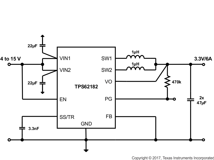
TPS62180 TPS62182 SLVSBB8_simplified.gif

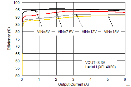
效率与输出电流间的关系

TPS62180 TPS62182 SLVSBB8_efficiency_lin.gif