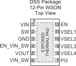
| VIN |
1 |
PWR |
VIN power supply pin. Connect this pin close to the VIN terminal of the input capacitor. A ceramic capacitor of 4.7 µF from this pin to GND is required. |
| SW |
2 |
OUT |
This is the switch pin which is connected to the internal MOSFET switches. Connect the inductor to this terminal. |
| GND |
3 |
PWR |
GND supply pin. Connect this pin close to the GND terminal of the input and output capacitor. |
| EN_VIN_SW |
4 |
IN |
This pin connects / disconnects the internal switch from VIN to pin VIN_SW. With EN_VIN_SW = Low, the switch is open. With EN_VIN_SW = High, the switch is closed connecting VIN with VIN_SW. If not used, the pin should be tied to GND. |
| VOUT |
5 |
IN |
Feedback pin for the internal feedback divider network and regulation loop. Connect this pin directly to the output capacitor with a short trace. |
| VIN_SW |
6 |
OUT |
This is the output of a switch connecting VIN with VIN_SW when EN_VIN_SW = High. If not used, leave this pin open. |
| PG |
7 |
OUT |
This is an open drain power good output. |
| VSEL4 |
8 |
IN |
Output voltage selection pins. See Table 1 and Table 2 for VOUT selection. These pins must be terminated. |
| VSEL3 |
9 |
IN |
| VSEL2 |
10 |
IN |
| VSEL1 |
11 |
IN |
| EN |
12 |
IN |
High level enables the devices, low level turns the device into shutdown mode. This pin must be terminated. |
| EXPOSED THERMAL PAD |
|
NC |
Not electrically connected to the IC. Connect this pad to GND and use it as a central GND plane. |
