ZHCSLJ2B September   2020  – July 2021 TPS62868 , TPS62869

PRODUCTION DATA  

  1. 特性
  2. 应用
  3. 说明
  4. Revision History
  5. Device Options
  6. Pin Configuration and Functions
  7. Specifications
    1. 7.1 Absolute Maximum Ratings
    2. 7.2 ESD Ratings
    3. 7.3 Recommended Operating Conditions
    4. 7.4 Thermal Information
    5. 7.5 Electrical Characteristics
    6. 7.6 I2C InterfaceTiming Characteristics
    7. 7.7 Typical Characteristics
  8. Detailed Description
    1. 8.1 Overview
    2. 8.2 Functional Block Diagram
    3. 8.3 Feature Description
      1. 8.3.1 Power Save Mode
      2. 8.3.2 Forced PWM Mode
      3. 8.3.3 100% Duty Cycle Mode Operation
      4. 8.3.4 Start-up
      5. 8.3.5 Switch Current Limit and HICCUP Short-Circuit Protection
      6. 8.3.6 Undervoltage Lockout (UVLO)
      7. 8.3.7 Thermal Warning and Shutdown
    4. 8.4 Device Functional Modes
      1. 8.4.1 Enable and Disable (EN)
      2. 8.4.2 Output Discharge
      3. 8.4.3 Start-Up Output Voltage and I2C Target Address Selection
        1. 8.4.3.1 TPS6286xxA Devices
        2. 8.4.3.2 TPS6286xxxC Devices
      4. 8.4.4 Select Output Voltage Registers (VID)
      5. 8.4.5 Power Good ( PG)
    5. 8.5 Programming
      1. 8.5.1 Serial Interface Description
      2. 8.5.2 Standard-, Fast-, and Fast-Mode Plus Protocol
      3. 8.5.3 HS-Mode Protocol
      4. 8.5.4 I2C Update Sequence
      5. 8.5.5 I2C Register Reset
    6. 8.6 Register Map
      1. 8.6.1 Target Address Byte
      2. 8.6.2 Register Address Byte
      3. 8.6.3 VOUT Register 1
      4. 8.6.4 VOUT Register 2
      5. 8.6.5 CONTROL Register
      6. 8.6.6 STATUS Register
  9. Application and Implementation
    1. 9.1 Application Information
    2. 9.2 Typical Application
      1. 9.2.1 Design Requirements
      2. 9.2.2 Detailed Design Procedure
        1. 9.2.2.1 Setting The Output Voltage
        2. 9.2.2.2 Output Filter Design
        3. 9.2.2.3 Inductor Selection
        4. 9.2.2.4 Capacitor Selection
      3. 9.2.3 Application Curves
    3. 9.3 Typical Application – TPS6286x0A and TPS6286x0xC Devices
      1. 9.3.1 Design Requirements
      2. 9.3.2 Detailed Design Procedure
        1. 9.3.2.1 Setting the Output Voltage
        2. 9.3.2.2 Output Filter Design
        3. 9.3.2.3 Inductor Selection
        4. 9.3.2.4 Capacitor Selection
      3. 9.3.3 Application Curves
  10. 10Power Supply Recommendations
  11. 11Layout
    1. 11.1 Layout Guidelines
    2. 11.2 Layout Example
      1. 11.2.1 Thermal Considerations
  12. 12Device and Documentation Support
    1. 12.1 Device Support
      1. 12.1.1 第三方米6体育平台手机版_好二三四免责声明
    2. 12.2 Documentation Support
      1. 12.2.1 Related Documentation
    3. 12.3 支持资源
    4. 12.4 接收文档更新通知
    5. 12.5 Trademarks
    6. 12.6 术语表
    7. 12.7 Electrostatic Discharge Caution
  13. 13Mechanical, Packaging, and Orderable Information

封装选项

机械数据 (封装 | 引脚)
散热焊盘机械数据 (封装 | 引脚)
订购信息

说明

TPS62868 和 TPS62869 器件是采用 I2C 接口的高频同步降压转换器,可提供高效、自适应和高功率密度解决方案。该转换器在中高负载条件下以 PWM 模式运行,并在轻负载时自动进入省电模式运行,从而在整个负载电流范围内保持高效率。该器件还可强制进入 PWM 模式运行,以实现最小的输出电压纹波。凭借其 DCS-Control 架构,这些器件可实现出色的负载瞬态性能并符合严格的输出电压精度要求。通过 I2C 接口和专用 VID 引脚,可快速调整输出电压,使负载的功耗适应相关应用不断变化的性能需求。

器件信息
器件型号封装(1)封装尺寸(标称值)
TPS62868QFN (9)1.5mm x 2.5mm x 1.0mm
TPS62869
如需了解所有可用封装,请参阅数据表末尾的可订购米6体育平台手机版_好二三四附录。
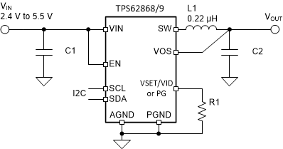
GUID-20200723-CA0I-D8JB-BFHD-V5SVQ9ZRQG7V-low.gif典型应用
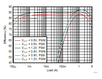
GUID-20200812-CA0I-LT6S-3NWZ-FXH2TPFJLJMV-low.gifVIN = 3.3V 时的效率