SBVS100E June 2008 – September 2015 TPS720
PRODUCTION DATA.
- 1 Features
- 2 Applications
- 3 Description
- 4 Revision History
- 5 Pin Configuration and Functions
- 6 Specifications
- 7 Detailed Description
- 8 Application and Implementation
- 9 Power Supply Recommendations
- 10Layout
- 11Device and Documentation Support
- 12Mechanical, Packaging, and Orderable Information
封装选项
机械数据 (封装 | 引脚)
散热焊盘机械数据 (封装 | 引脚)
- DRV|6
订购信息
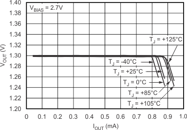
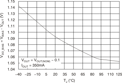
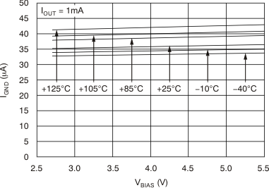
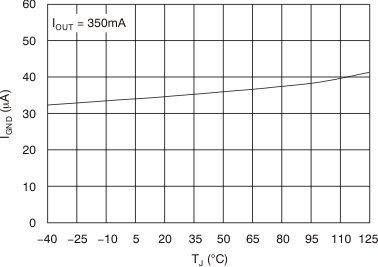
6.6 Typical Characteristics
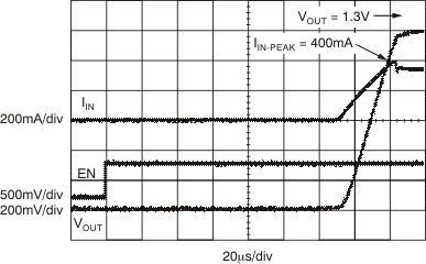
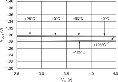
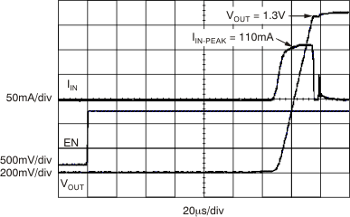
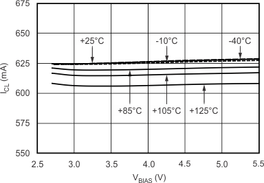
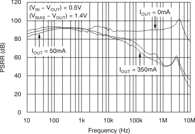
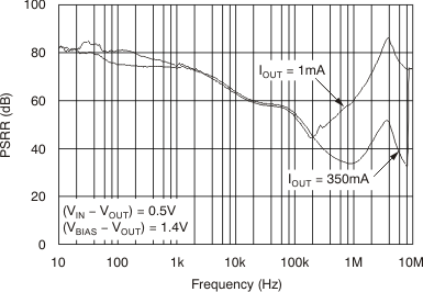
Over operating temperature range (TJ = –40°C to 125°C), VBIAS = (VOUT + 1.4 V) or 2.5 V (whichever is greater); VIN = VOUT + 0.5 V, IOUT = 1 mA, VEN = 1.1 V, COUT = 2.2 μF, unless otherwise noted. Typical values are at TJ = 25°C.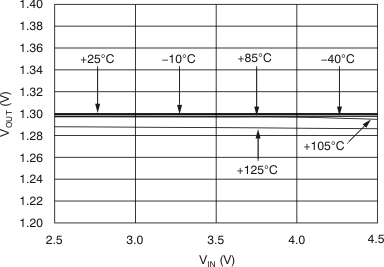
| IOUT = 0 mA |
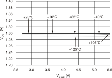
| IOUT = 0 mA |
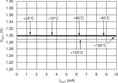
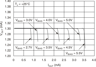
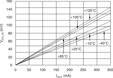
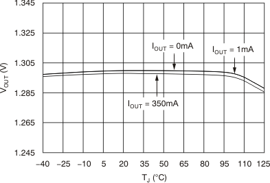
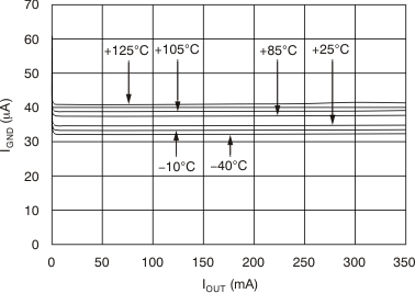
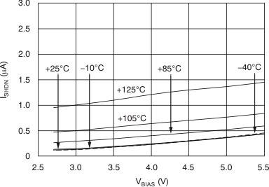
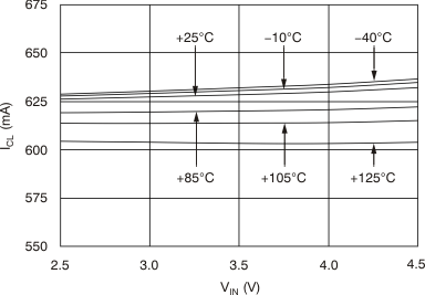
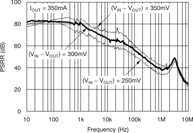
vs Frequency (TPS72015YZU)
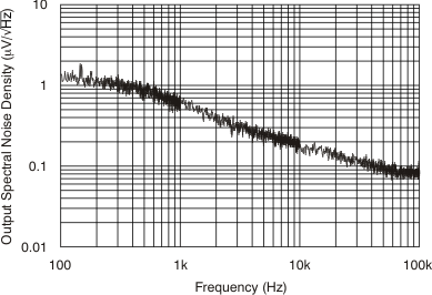
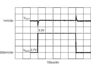
| VIN = 1.8 V | VOUT = 1.3 V | VBIAS = 2.7 V to 3.3 V |
| VBIAS Slew Rate = 600 m/μs | IOUT = 350 mA | |
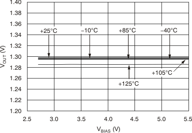
| IOUT = 350 mA |

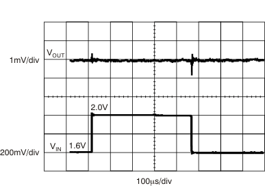
| VIN = 1.6 to 2 V | VOUT = 1.3 V | VBIAS = 2.7 V |
| VIN Slew Rate = 1 V/μs | IOUT = 350 mA |
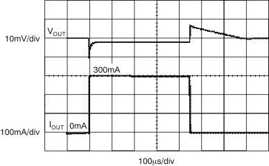
| VIN = 1.8 V | VOUT = 1.3 V | VBIAS = 2.7 V |
| tRISE = 1 μs |
