ZHCSIS2B september 2018 – december 2020 TPS7A11
PRODUCTION DATA
- 1
- 1 特性
- 2 应用
- 3 说明
- 4 Revision History
- 5 Pin Configuration and Functions
- 6 Specifications
- 7 Detailed Description
-
8 Application and Implementation
- 8.1
Application Information
- 8.1.1 Recommended Capacitor Types
- 8.1.2 Input and Output Capacitor Requirements
- 8.1.3 Load Transient Response
- 8.1.4 Dropout Voltage
- 8.1.5 Behavior During Transition From Dropout Into Regulation
- 8.1.6 Undervoltage Lockout Circuit Operation
- 8.1.7 Power Dissipation (PD)
- 8.1.8 Estimating Junction Temperature
- 8.1.9 Recommended Area for Continuous Operation
- 8.2 Typical Application
- 8.1
Application Information
- 9 Power Supply Recommendations
- 10Layout
- 11Device and Documentation Support
- Mechanical, Packaging, and Orderable Information
封装选项
机械数据 (封装 | 引脚)
散热焊盘机械数据 (封装 | 引脚)
- DRV|6
订购信息
7.3.1.1 Global Undervoltage Lockout (UVLO)
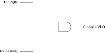
The TPS7A11 uses two undervoltage lockout circuits: one on the BIAS pin and one on the IN pin to prevent the device from turning on before either VBIAS and VIN rise above their lockout voltages. The two UVLO signals are connected internally through an AND gate, as shown in Figure 7-1, that allows the device to be turned off when either of these rails are below the lockout voltage.

Figure 7-1 Global UVLO circuit