ZHCSJ50C December   2018  – December 2022 TPS7A25

PRODUCTION DATA  

  1. 特性
  2. 应用
  3. 说明
  4. Revision History
  5. Pin Configuration and Functions
  6. Specifications
    1. 6.1 Absolute Maximum Ratings
    2. 6.2 ESD Ratings
    3. 6.3 Recommended Operating Conditions
    4. 6.4 Thermal Information
    5. 6.5 Electrical Characteristics
  7. Typical Characteristics
  8. Detailed Description
    1. 8.1 Overview
    2. 8.2 Functional Block Diagrams
    3. 8.3 Feature Description
      1. 8.3.1 Output Enable
      2. 8.3.2 Dropout Voltage
      3. 8.3.3 Current Limit
      4. 8.3.4 Undervoltage Lockout (UVLO)
      5. 8.3.5 Thermal Shutdown
      6. 8.3.6 Power Good
      7. 8.3.7 Active Overshoot Pulldown Circuitry
    4. 8.4 Device Functional Modes
      1. 8.4.1 Device Functional Mode Comparison
      2. 8.4.2 Normal Operation
      3. 8.4.3 Dropout Operation
      4. 8.4.4 Disabled
        1.       Application and Implementation
          1. 9.1 Application Information
            1. 9.1.1 Adjustable Device Feedback Resistors
            2. 9.1.2 Recommended Capacitor Types
            3. 9.1.3 Input and Output Capacitor Requirements
            4. 9.1.4 Reverse Current
            5. 9.1.5 Feed-Forward Capacitor (CFF)
            6. 9.1.6 Power Dissipation (PD)
            7. 9.1.7 Estimating Junction Temperature
            8. 9.1.8 Special Consideration for Line Transients
          2. 9.2 Typical Application
            1. 9.2.1 Design Requirements
            2. 9.2.2 Detailed Design Procedure
              1. 9.2.2.1 Transient Response
              2. 9.2.2.2 Selecting Feedback Divider Resistors
              3. 9.2.2.3 Thermal Dissipation
            3. 9.2.3 Application Curve
          3. 9.3 Power Supply Recommendations
          4. 9.4 Layout
            1. 9.4.1 Layout Guidelines
            2. 9.4.2 Layout Examples
  9. Device and Documentation Support
    1. 9.1 Device Support
      1. 9.1.1 Device Nomenclature
    2. 9.2 Documentation Support
      1. 9.2.1 Related Documentation
    3. 9.3 接收文档更新通知
    4. 9.4 支持资源
    5. 9.5 Trademarks
    6. 9.6 Electrostatic Discharge Caution
    7. 9.7 术语表
  10. 10Mechanical, Packaging, and Orderable Information
    1. 10.1 Mechanical Data

封装选项

请参考 PDF 数据表获取器件具体的封装图。

机械数据 (封装 | 引脚)
  • DRV|6
散热焊盘机械数据 (封装 | 引脚)
订购信息

说明

TPS7A25 低压降 (LDO) 线性稳压器集 2.4V 至 18V 输入电压范围和极低静态电流 (IQ) 特性于一体。这些特性能帮助现代电器满足日益严苛的能源要求,并有助于延长便携式电源解决方案的电池寿命。

TPS7A25 有固定电压和可调节电压两种版本可供选用。为获得更大的灵活性或更高的输出电压,可调节电压版本使用反馈电阻器将输出电压设置为 1.24 V 到 17.64V 之间。两种版本都具有 1% 的输出调节精度,可对微控制器 (MCU) 基准电压进行精密调节。

在电流为 300mA 时,TPS7A25 LDO 的最大压降小于 340mV,因此它比标准线性稳压器的工作效率更高。此最大压降使得在 5.4V 输入电压 (VIN) 至 5.0V 输出电压 (VOUT) 范围内的效率达到了 92.5%。

电源正常状态 (PG) 指示灯可以用来将 MCU 保持在复位状态,直到电源正常,或用于电源定序。PG 引脚为开漏输出;因此,该引脚很容易进行电平位移,以便通过 VOUT 以外的导轨进行监控。内置电流限制和热关断有助于在发生负载短路或故障时保护稳压器。

如需更高的输出电流选项,请考虑 TPS7A26

封装信息(1)
器件型号 封装 封装尺寸(NOM)
TPS7A25 DRV(WSON,6) 2.00mm x 2.00mm
如需了解所有可用封装,请参阅数据表末尾的封装选项附录。
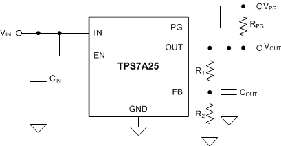
GUID-77182093-4D9A-4EFA-944B-727E3635924E-low.gif典型应用电路