ZHCSOT7 November 2021 TPS7A44
PRODUCTION DATA
- 1 特性
- 2 应用
- 3 说明
- 4 Revision History
- 5 Pin Configuration and Functions
- 6 Specifications
- 7 Detailed Description
- 8 Application and Implementation
- 9 Power Supply Recommendations
- 10Layout
- 11Device and Documentation Support
- 12Mechanical, Packaging, and Orderable Information
7.3.2 Precision Enable
The TPS7A44 features a precision enable circuit. The enable pin (EN) is active high; thus, enable the device by forcing the voltage of the enable pin to exceed the VEN(HI) voltage; see the Section 6.5 table. Turn off the device by forcing the voltage of the enable pin to drop below the VEN(LOW) voltage; see the Section 6.5 table. This device has an internal pullup resistor to the IN pin that enables the device when the EN pin is left floating.
If this pin is tied to the IN pin, the input voltage must not exceed 18 V; see the Section 6.3 table.
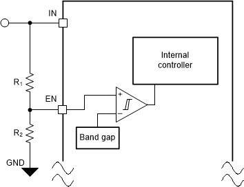
As shown in Figure 7-3, an external resistor divider circuit can be used to enable the device using the input voltage.
 Figure 7-3 Enable the Device Using the
Input Voltage
Figure 7-3 Enable the Device Using the
Input VoltageThe VEN(HI) (maximum) and VEN(LOW) (minimum) thresholds along with the application input voltage can be used to set the R1 to R2 resistor divider ratio. The values of the R2 and R1 resistors can also be optimized to minimize the leakage current through the divider.