ZHCSDR0 April 2015 TPS92513 , TPS92513HV
PRODUCTION DATA.
- 1 特性
- 2 应用范围
- 3 说明
- 4 简化电路原理图
- 5 修订历史记录
- 6 Pin Configuration and Functions
- 7 Specifications
-
8 Detailed Description
- 8.1 Overview
- 8.2 Functional Block Diagram
- 8.3
Feature Description
- 8.3.1 Undervoltage Lockout and Low Power Shutdown (UVLO Pin)
- 8.3.2 Adjustable Switching Frequency (RT/CLK Pin)
- 8.3.3 Synchronizing the Switching Frequency to an External Clock (RT/CLK Pin)
- 8.3.4 Adjustable LED Current (IADJ and ISENSE Pins)
- 8.3.5 PWM Dimming (PDIM Pin)
- 8.3.6 External Compensation (COMP Pin)
- 8.3.7 Overcurrent Protection
- 8.3.8 Overtemperature Protection
- 8.4 Device Functional Modes
-
9 Application and Implementation
- 9.1 Application Information
- 9.2 Typical Application
- 9.3 Design Requirements
- 9.4
Detailed Design Procedure
- 9.4.1 Standard Component Selection
- 9.4.2 Calculate UVLO Resistor Values
- 9.4.3 Calculate the RT Resistor Value (RRT)
- 9.4.4 Calculate the ISENSE Resistor Value (R(ISENSE))
- 9.4.5 Calculate the Inductor Value and Operating Parameters (L)
- 9.4.6 Calculate the Minimum Input Capacitance and the Required RMS Current Rating (CIN)
- 9.4.7 Calculate the Output Capacitor Value (COUT)
- 9.4.8 Calculate the Diode Power Dissipation (D)
- 9.5 Application Curves
- 10Power Supply Recommendations
- 11Layout
- 12器件和文档支持
- 13机械、封装和可订购信息
9 Application and Implementation
NOTE
Information in the following applications sections is not part of the TI component specification, and TI does not warrant its accuracy or completeness. TI’s customers are responsible for determining suitability of components for their purposes. Customers should validate and test their design implementation to confirm system functionality.
9.1 Application Information
This section describes power component selection not discussed in the Feature Description section.
9.1.1 Inductor Selection
The value of the buck inductor impacts the peak-to-peak ripple-current amplitude. The peak inductor current is used in current mode control and to maintain a good signal to noise ratio it is recommended that the peak-to-peak ripple current (IREquation 18) is greater than 75 mA for dependable operation. This allows the control system to have an adequate current signal even at the lowest input voltage. Equation 18 calculates the value for the buck inductance given the minimum ripple current of IR = 75 mA. Enter the lowest input voltage and the highest output voltage to yield the maximum inductance value.

Calculate the maximum inductor value for the particular application and choose the next lowest standard value for applications requiring low ripple current. Choose a lower value for size sensitive applications that can tolerate higher LED current ripple or use larger output capacitors. With the chosen value the user can calculate the actual inductor current ripple using Equation 19.

The inductor RMS current and saturation current ratings must be greater than those seen in the application. This ensures that the inductor does not overheat or saturate. During power-up, transient conditions, or fault conditions, the inductor current can exceed its normal operating current. For this reason, the most conservative approach is to specify an inductor with a saturation current rating equal to or greater than the converter current limit. This is not always possible due to application size limitations. The peak inductor current and the RMS current equations are shown in Equation 20 and Equation 21.


9.1.2 Input Capacitor Selection
The TPS92513 requires a high-quality ceramic, type X5R or X7R, input decoupling capacitor of at least 2 µF of effective capacitance per 1 A of output current. Ceramic capacitance tends to decrease as the applied dc voltage increases. This depreciation must be accounted for to ensure that the minimum input capacitance is satisfied. In some applications, additional capacitance is needed to provide bulk energy storage such as high current PWM dimming applications. The input capacitor voltage rating must be greater than the maximum input voltage and have a ripple current rating greater than the maximum input current ripple of the converter. The RMS input ripple current is calculated in Equation 22, where D is the duty cycle (output voltage divided by input voltage). The maximum RMS input ripple current can be calculated by using the minimum input voltage for the application.

The input capacitance (CIN) is inversely proportional to the input ripple voltage of the converter. The peak-to-peak input ripple voltage can be calculated as shown in Equation 23. Additionally, this equation can be used to solve for the required input capacitance to keep the input ripple voltage to a defined limit.

9.1.3 Output Capacitor Selection
During start-up, the TPS92513 uses the discharged output capacitor as a charging path for the BOOT capacitor. In order to ensure that the BOOT capacitor charges and that the converter begins switching immediately, the value of the output capacitor should be 10 times larger than the BOOT capacitor. If the BOOT capacitor is 0.1 µF, then the minimum output capacitor should be 1 µF for the fastest startup time. If the output capacitor is chosen to be a smaller value or none at all, then the BOOT capacitor can charge through the LED string itself. However, this method of charging the BOOT capacitor will result in longer startup times.
The output capacitor also reduces the high-frequency ripple current through the LED string. Various guidelines disclose how much high-frequency ripple current is acceptable in the LED string. Excessive ripple current in the LED string increases the RMS current in the LED string, and therefore the LED temperature also increases. First, calculate the total dynamic resistance of the LED string (RLED) using the LED manufacturer’s data sheet. Second, calculate the required impedance of the output capacitor (ZOUT) given the acceptable peak-to-peak ripple current through the LED string, ΔILED. IRIPPLE is the peak-to-peak inductor ripple current as calculated previously in Inductor Selection. Third, calculate the minimum effective output capacitance required. Finally, increase the output capacitance appropriately due to the derating effect of applied dc voltage. See Equation 24, Equation 25, and Equation 26.


9.1.4 Rectifier Diode Selection
The rectifier diode conducts the inductor current only during the high-side MOSFET off-time. The rectifier diode must have a reverse voltage rating greater than the maximum input voltage and a current rating greater than the peak inductor current. A Schottky diode is recommended for highest efficiency and optimal performance. The package size chosen for the rectifier diode must be capable of handling the power dissipation of the diode. The diode power dissipation is equal to the average diode current times the diode forward voltage, VF. See Equation 27 and Equation 28.


When calculating the diode average current, the worst case duty cycle, D, for the diode should be used. D should be calculated using the maximum input voltage for the application in this case.
9.1.5 Output Protection Clamp (Optional)
In the event of an output open circuit during normal operation the output voltage will rise up to the input voltage. This is a safe operating mode provided the output capacitor can sustain the voltage without damage. However, the inductor will still have energy stored at the moment of the event. This can cause significant ringing between the inductor and output capacitor that can shoot higher than VIN. To prevent this, a single Schottky diode from VOUT to VIN can be used to clamp the ringing. This diode should be rated for at least 500 mA and have a voltage rating greater than or equal to the voltage rating of the rectifier diode. A zener diode across the output capacitor can also be used to clamp the output voltage to a lower level. The output will clamp at the zener voltage plus the ISENSE voltage since when the zener begins to conduct it will pull the ISENSE pin up and reduce the duty cycle.
9.2 Typical Application
The TPS92513 is a switching regulator designed to provide tight current regulation and high performance over a wide range of conditions. The following application is a design example for a wide input voltage range, high current regulator.
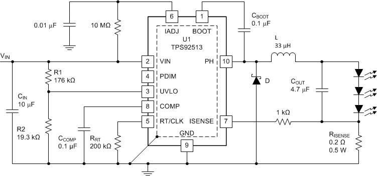
Figure 13 shows the schematic for the wide input voltage range converter with the design requirements below. A detailed design procedure to calculate various component values follows.
 Figure 13. High Current, Low LED Current Ripple Buck Converter
9.3 Design Requirements
- VIN range of 12 V to 48 V
- UVLO set to 12 V with 0.8 V hysteresis
- 3 LED output, 9.7 V stack, VOUT = 10 V
- 1.5A LED current (at VISENSE = 300 mV for best accuracy)
- Switching frequency of 570 kHz
- LED current ripple of 10 mA or less
9.4 Detailed Design Procedure
This section provides a detailed design procedure for selecting the component values for the application with the given design requirements.
9.4.1 Standard Component Selection
Choose a 0.1 µF ceramic capacitor with a 10 V or greater rating for CCOMP and CBOOT. Connect IADJ to VIN through a 10 MΩ resistor to clamp it at 1.8 V and provide an ISENSE voltage regulation point of 300 mV. Connect a 10 nF capacitor from IADJ to ground. Connect ISENSE to R(ISENSE) through a 1 kΩ resistor.
9.4.2 Calculate UVLO Resistor Values
Using Equation 1 and Equation 2 the UVLO resistors R1 and R2 can be calculated using Equation 29, Equation 30, and the following parameters:
- VSTART = 12 V
- VSTOP = 11.2 V
- VHYS = 0.8 V

Choose the closest standard 1% value of 176 kΩ for R1. This value can then be used to calculate the value of R2 as shown in Equation 30.

Choose the closest standard 1% value of 19.3 kΩ for R2.
9.4.3 Calculate the RT Resistor Value (RRT)
The desired switching frequency is 570 kHz, so the value of RRT can be calculated using Equation 5 as shown in Equation 31.

Choose the closest standard 1% value of 200 kΩ for RRT.
9.4.4 Calculate the ISENSE Resistor Value (R(ISENSE))
This design uses a VISENSE voltage of 300 mV and the desired LED current (ILED) is 1.5 A. Given these values the sense resistor value can be calculated using Equation 8 as shown in Equation 32.

0.2 Ω is a standard 1% resistor value. The power dissipation is VISENSE multiplied by ILED, in this case 0.45 W. Choose a 0.5 W or greater resistor.
9.4.5 Calculate the Inductor Value and Operating Parameters (L)
For this application, low LED ripple current is important. One way to reduce LED ripple current is to reduce inductor ripple current. For this low ripple current application, the maximum inductor value (minimum 75 mA current ripple IR) will be calculated and the next lower value will be used. The maximum inductor value can be calculated using Equation 18 as shown in Equation 33.

Choose the next lowest standard value of 33 µH. Now the actual inductor current ripple, the peak inductor current, and the RMS inductor current can be calculated using Equation 19, Equation 20, and Equation 21 as shown in Equation 34, Equation 35, and Equation 36.


The inductor chosen should have a saturation current rating higher than IL_PEAK and a DC current rating higher than IL_RMS.
9.4.6 Calculate the Minimum Input Capacitance and the Required RMS Current Rating (CIN)
Given a minimum of 2 µF of capacitance for every 1 A of LED current, a 1.5 A design would require a minimum of 3 µF. To account for ceramic capacitor tolerances and capacitance drops due to bias voltage this capacitance should be at least doubled. Higher values will also give better overall performance. Choose a 10 µF capacitor with a voltage rating of 50 V or greater. Using Equation 13, Equation 22, and Equation 23 the user can calculate the RMS current rating required for the capacitor and the resulting input voltage ripple as shown in Equation 38 and Equation 39.


9.4.7 Calculate the Output Capacitor Value (COUT)
The required output capacitor value to get the required LED ripple current can be calculated by first determining the dynamic resistance of the LEDs used, RLED, by using the forward voltage versus forward current graph in the manufacturer’s datasheet. Place a tangent line on the curve at the forward current required to get the slope and the corresponding ΔV and ΔF. For this design example, the RLED is 0.22 Ω per LED. So the total RLED is 0.22 Ω X 3, or 0.66 Ω. Then find the required output impedance, ZCOUT, using Equation 25 as shown in Equation 40. Using the required ZCOUT calculate the minimum output capacitance using Equation 26 as shown in Equation 41.


Choose a 4.7 µF ceramic capacitor with a X5R or X7R dielectric and 16 V or greater voltage rating.
9.4.8 Calculate the Diode Power Dissipation (D)
The maximum input voltage is 48 V, so a 60 V or greater Schottky diode should be used for this application. Calculate the required current rating and power dissipation to size the diode correctly. This should be done at the maximum input voltage since that is where the diode conducts for the most time and will have the highest power dissipation. The duty cycle, D, at the maximum input voltage is 10 V/48 V, or 0.208. Using this duty cycle and Equation 27 calculate the average diode current, ID_AVE, as shown in Equation 42. Then calculate the diode power dissipation, PDIODE, using Equation 28 as shown in Equation 43.


The power dissipation calculation is assuming a diode forward voltage drop, VF, of 0.7 V. If a diode with a different forward drop is chosen the calculation should be re-done. Choose a Schottky diode with a 1.5 A or greater current rating that can dissipate at least 1 W of power.
9.5 Application Curves

| , |

