ZHCSDR0 April 2015 TPS92513 , TPS92513HV
PRODUCTION DATA.
- 1 特性
- 2 应用范围
- 3 说明
- 4 简化电路原理图
- 5 修订历史记录
- 6 Pin Configuration and Functions
- 7 Specifications
-
8 Detailed Description
- 8.1 Overview
- 8.2 Functional Block Diagram
- 8.3
Feature Description
- 8.3.1 Undervoltage Lockout and Low Power Shutdown (UVLO Pin)
- 8.3.2 Adjustable Switching Frequency (RT/CLK Pin)
- 8.3.3 Synchronizing the Switching Frequency to an External Clock (RT/CLK Pin)
- 8.3.4 Adjustable LED Current (IADJ and ISENSE Pins)
- 8.3.5 PWM Dimming (PDIM Pin)
- 8.3.6 External Compensation (COMP Pin)
- 8.3.7 Overcurrent Protection
- 8.3.8 Overtemperature Protection
- 8.4 Device Functional Modes
-
9 Application and Implementation
- 9.1 Application Information
- 9.2 Typical Application
- 9.3 Design Requirements
- 9.4
Detailed Design Procedure
- 9.4.1 Standard Component Selection
- 9.4.2 Calculate UVLO Resistor Values
- 9.4.3 Calculate the RT Resistor Value (RRT)
- 9.4.4 Calculate the ISENSE Resistor Value (R(ISENSE))
- 9.4.5 Calculate the Inductor Value and Operating Parameters (L)
- 9.4.6 Calculate the Minimum Input Capacitance and the Required RMS Current Rating (CIN)
- 9.4.7 Calculate the Output Capacitor Value (COUT)
- 9.4.8 Calculate the Diode Power Dissipation (D)
- 9.5 Application Curves
- 10Power Supply Recommendations
- 11Layout
- 12器件和文档支持
- 13机械、封装和可订购信息
1 特性
- 集成型 220mΩ 高侧金属氧化物半导体场效应晶体管 (MOSFET)
- 4.5V 至 42V 输入电压范围
(TPS92513HV 为 4.5V 至 60V) - 0V 至 300mV 可调基准电压
- ±5% LED 电流精度
- 100kHz 至 2MHz 开关频率范围
- 专用脉宽调制 (PWM) 调光输入
- 可调节欠压闭锁
- 过流保护
- 过热保护
- MSOP-10 封装,采用 PowerPAD™
2 应用范围
- 街道照明
- 紧急/出口照明
- 一般工业和商业用照明
- 零售照明
- 电器照明
- 运输照明
- 立体发光字
- 光条
3 说明
TPS92513/HV 为 1.5A 降压电流稳压器,其集成有 MOSFET,用于驱动高电流 LED。 这两款 LED 驱动器的输入电压上限分别为 42V 和 60V (HV),并且可在峰值电流模式控制下以用户选择的固定频率工作,同时可提供出色的线路和负载调节性能。
TPS92513/HV LED 驱动器特有分别用于模拟调光和脉宽调制 (PWM) 调光的独立输入,并且不会影响到亮度控制,对比度分别高达 10:1 和 100:1 以上。 PWM 输入符合低压逻辑标准,可轻松连接各类微控制器。 通过 IADJ 输入,可使用 0V 至 1.8V 的外部信号在 0V 至 300mV 范围内调整模拟 LED 电流设定值。
对于使用两个或两个以上 TPS92513/HV LED 驱动器的多灯串应用,可通过外部时钟来过驱动内部振荡器,以确保所有转换器工作在同一频率下,从而降低出现拍频的几率并简化系统电磁干扰 (EMI) 滤波设计。 该器件具有一个带滞后功能的可调节输入欠压闭锁 (UVLO) 引脚,可根据具体的电源电压条件灵活设置起始/停止电压。
TPS92513 具有逐周期过流保护和热关断保护。 该器件采用 10 引脚 HVSSOP PowerPAD™ 封装。
器件信息(1)
| 器件型号 | 封装 | 封装尺寸(标称值) |
|---|---|---|
| TPS92513 | HVSSOP (10) | 5.00mm x 3.00mm |
| TPS92513HV |
- 要了解所有可用封装,请见数据表末尾的可订购米6体育平台手机版_好二三四附录。
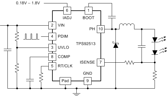
4 简化电路原理图

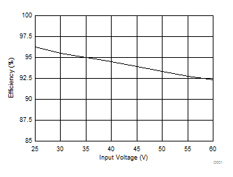
效率与输入电压间的关系
1.5A 电流下的 7 个白色 LED (VOUT = 23V)
