ZHCSMP8B November   2020  – March 2021 TPSM5D1806

PRODUCTION DATA  

  1. 特性
  2. 应用
  3. 说明
  4. Revision History
  5. Pin Configuration and Functions
  6. Specifications
    1. 6.1 Absolute Maximum Ratings
    2. 6.2 ESD Ratings
    3. 6.3 Recommended Operating Conditions
    4. 6.4 Thermal Information
    5. 6.5 Electrical Characteristics
    6. 6.6 Typical Characteristics (VIN = 12 V)
    7. 6.7 Typical Characteristics (VIN = 5 V)
  7. Detailed Description
    1. 7.1 Overview
    2. 7.2 Functional Block Diagram
    3. 7.3 Feature Description
      1. 7.3.1  Adjustable Output Voltage
      2. 7.3.2  Frequency Selection
        1. 7.3.2.1 Synchronization
        2. 7.3.2.2 Allowable Switching Frequency
      3. 7.3.3  Minimum and Maximum Input Voltage
      4. 7.3.4  Recommended Settings
      5. 7.3.5  Device Mode Configuration
        1. 7.3.5.1 MODE1 (Operating Mode and Phase Position)
        2. 7.3.5.2 MODE2 (Setting the Switching Frequency)
      6. 7.3.6  Input Capacitors
      7. 7.3.7  Minimum Required Output Capacitance
      8. 7.3.8  Ambient Temperature Versus Total Power Dissipation
      9. 7.3.9  Remote Sense
      10. 7.3.10 Enable (EN) and Under Voltage Lockout (UVLO)
      11. 7.3.11 Soft Start
      12. 7.3.12 Power Good
      13. 7.3.13 Safe Start-up into Pre-Biased Outputs
      14. 7.3.14 BP5
      15. 7.3.15 Overcurrent Protection
      16. 7.3.16 Thermal Shutdown
    4. 7.4 Device Functional Modes
      1. 7.4.1 Active Mode
      2. 7.4.2 Shutdown Mode
  8. Application and Implementation
    1. 8.1 Application Information
    2. 8.2 Typical Application (Dual Outputs)
      1. 8.2.1 Design Requirements
      2. 8.2.2 Detailed Design Procedure
        1. 8.2.2.1 Custom Design With WEBENCH® Tools
        2. 8.2.2.2 Output Voltage Setpoint
        3. 8.2.2.3 Input Capacitors
        4. 8.2.2.4 Output Capacitor Selection
      3. 8.2.3 Typical Application (Paralleled Outputs)
        1. 8.2.3.1 Design Requirements
        2. 8.2.3.2 Detailed Design Procedure
          1. 8.2.3.2.1 Output Voltage Setpoint
          2. 8.2.3.2.2 Input Capacitors
          3. 8.2.3.2.3 Output Capacitor Selection
  9. Power Supply Recommendations
  10. 10Layout
    1. 10.1 Layout Guidelines
    2. 10.2 Layout Examples
      1. 10.2.1 Package Specifications
      2. 10.2.2 EMI
  11. 11Device and Documentation Support
    1. 11.1 Device Support
      1. 11.1.1 Development Support
        1. 11.1.1.1 Custom Design With WEBENCH® Tools
    2. 11.2 接收文档更新通知
    3. 11.3 支持资源
    4. 11.4 Trademarks
    5. 11.5 静电放电警告
    6. 11.6 术语表
  12. 12Mechanical, Packaging, and Orderable Information

封装选项

机械数据 (封装 | 引脚)
散热焊盘机械数据 (封装 | 引脚)
订购信息

说明

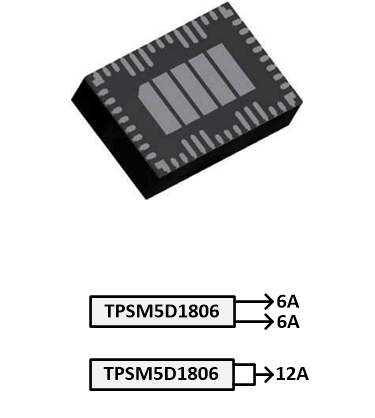
TPSM5D1806 双路 6A 输出电源模块是一款高度集成且灵活的直流/直流电源,采用紧凑型 8mm × 5.5mm × 1.8mm QFN 封装。输入电压范围为 4.5V 至 15V,因此可对宽电压范围的中间总线以及标准 5V 和 12V 电压轨进行电压转换。两个 6A 输出可以针对两个单独的电源轨分别配置,也可以合并为一个两相 12A 输出。

具有出色封装布局的低厚度 51 引脚 QFN 封装可提高热性能。该封装的所有信号引脚均分布在外围,器件下方有一些大型散热焊盘,可在制造过程中实现简单布局和轻松处理。

集成的电源设计省去了设计流程中的环路补偿和磁性元件选型。该器件为每个输出提供了独立的使能控制和电源正常信号。开关频率和相位偏移可以使用引脚束带进行配置。该器件还提供了过流和热关断保护。

器件信息
器件型号封装(1)封装尺寸(标称值)
TPSM5D1806QFN8mm × 5.5mm × 1.8mm
如需了解所有可用封装,请参阅数据表末尾的可订购米6体育平台手机版_好二三四附录。
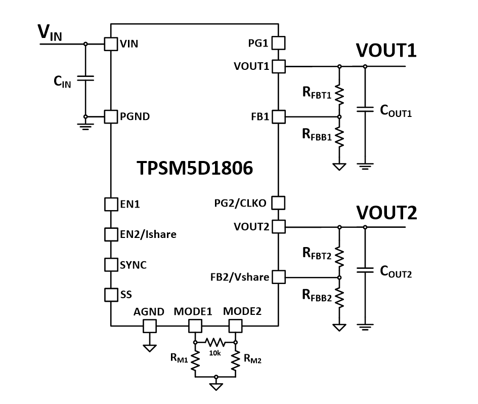
GUID-0D5098DC-8C9E-48F1-B9AE-CF715F99C8F7-low.gif双路输出简化版原理图
GUID-20201109-CA0I-FM15-FCC4-NHBXV5G8XNCD-low.gif输出配置