ZHCSCH8 May   2014 TRF37C73

PRODUCTION DATA.  

  1. 特性
  2. 应用范围
  3. 说明
  4. 修订历史记录
  5. Pin Configuration and Functions
  6. Specifications
    1. 6.1 Absolute Maximum Ratings
    2. 6.2 Handling Ratings
    3. 6.3 Recommended Operating Conditions
    4. 6.4 Thermal Information
    5. 6.5 Electrical Characteristics
    6. 6.6 Timing Requirements
    7. 6.7 Typical Characteristics
  7. Detailed Description
    1. 7.1 Overview
    2. 7.2 Functional Block Diagram
    3. 7.3 Feature Description
    4. 7.4 Device Functional Modes
      1. 7.4.1 Power Down
  8. Applications and Implementation
    1. 8.1 Application Information
    2. 8.2 Typical Application
      1. 8.2.1 Design Requirements
      2. 8.2.2 Detailed Design Procedure
      3. 8.2.3 Application Curve
  9. Power Supply Recommendations
  10. 10Layout
    1. 10.1 Layout Guidelines
    2. 10.2 Layout Example
  11. 11器件和文档支持
    1. 11.1 Trademarks
    2. 11.2 Electrostatic Discharge Caution
    3. 11.3 Glossary
  12. 12机械封装和可订购信息

封装选项

机械数据 (封装 | 引脚)
散热焊盘机械数据 (封装 | 引脚)
订购信息

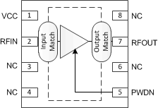
5 Pin Configuration and Functions

DSG PACKAGE
(TOP VIEW)
Package.gif

Pin Functions

PIN DESCRIPTION
NAME NO.
VCC 1 DC Bias.
RFIN 2 RF input. Connect to an RF source through a DC-blocking capacitor. Internally matched to 50 Ω.
NC 3, 4, 6, 8 No electrical connection. Connect pad to GND for board level reliability integrity.
PWDN 5 When high the device is in power down state. When LOW or NC the device is in active state. Internal pulldown resistor to GND.
RFOUT 7 RF Output and DC Bias (VCC). Connect to DC supply through an RF choke inductor. Connect to output load through a DC-blocking capacitor. Internally matched to 50 Ω.
GND PowerPAD™ RF and DC GND. Connect to PCB ground plane.