ZHCSCV1A June 2014 – July 2014 TSC2013-Q1
PRODUCTION DATA.
- 1 特性
- 2 应用
- 3 说明
- 4 修订历史记录
- 5 Pin Configurations and Functions
-
6 Specifications
- 6.1 Absolute Maximum Ratings
- 6.2 Handling Ratings
- 6.3 Recommended Operating Conditions
- 6.4 Thermal Information
- 6.5 Electrical Characteristics
- 6.6 Timing Requirements — I2C Standard Mode (ƒ(SCL) = 100 kHz)
- 6.7 Timing Requirements — I2C Fast Mode (ƒ(SCL) = 400 kHz)
- 6.8 Timing Requirements — I2C High-Speed Mode (ƒ(SCL) = 1.7 MHz)
- 6.9 Timing Requirements — I2C High-Speed Mode (ƒ(SCL) = 3.4 MHz)
- 6.10 Typical Characteristics
-
7 Detailed Description
- 7.1 Overview
- 7.2 Functional Block Diagram
- 7.3 Feature Description
- 7.4 Device Functional Modes
- 7.5 Programming
- 7.6
Register Maps
- 7.6.1 Configuration and Status Registers
- 7.6.2 Data Registers
-
8 Application and Implementation
- 8.1 Application Information
- 8.2
Typical Application
- 8.2.1 Design Requirements
- 8.2.2 Detailed Design Procedure
- 8.2.3 Application Curves
- 9 Power Supply Recommendations
- 10Layout
- 11器件和文档支持
- 12机械封装和可订购信息
封装选项
机械数据 (封装 | 引脚)
散热焊盘机械数据 (封装 | 引脚)
- RSA|16
订购信息
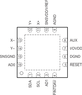
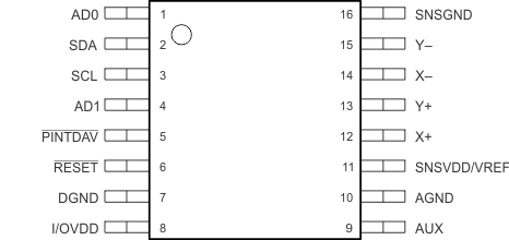
5 Pin Configurations and Functions
16-Pin VQFN With Thermal Pad
RSA Package
Top View

16-Pin TSSOP
PW Package
Top View

Pin Functions
| PIN | I/O | ADC | DESCRIPTION | ||
|---|---|---|---|---|---|
| NAME | RSA | PW | |||
| AD0 | 16 | 1 | I | D | I2C bus TSC address input bit 0 |
| AD1 | 3 | 4 | I | D | I2C bus TSC address input bit 1 |
| AGND | 9 | 10 | — | — | Analog, digital, and ESD ground(1) |
| AUX | 8 | 9 | — | A | Auxiliary channel |
| DGND | 6 | 7 | — | — | No internal connection. Connect this pin to analog ground for mechanical stability. |
| I/OVDD | 7 | 8 | I | — | Digital interface voltage |
| PINTDAV | 4 | 5 | O | D | Interrupt output. Data available or the pen-detect interrupt (PENIRQ), depending on setting. Pin polarity is active-low. |
| RESET | 5 | 6 | I | D | External hardware reset input (active-low). |
| SDA | 1 | 2 | I/O | D | Serial data I/O |
| SCL | 2 | 3 | I | D | Serial clock |
| SNSGND | 15 | 16 | — | — | Sensor driver return |
| SNSVDD/VREF | 10 | 11 | I | — | Power supply for sensor drivers and other analog blocks |
| X+ | 11 | 12 | — | A | X+ channel |
| X– | 13 | 14 | — | A | X– channel |
| Y+ | 12 | 13 | — | A | Y+ channel |
| Y– | 14 | 15 | — | A | Y– channel |
(1) For optimized system IEC ESD performance, contact Texas Instruments for schematic and layout reviews and suggestions.