SLLSEV4 February 2017 TUSB319-Q1
PRODUCTION DATA.
- 1 Features
- 2 Applications
- 3 Description
- 4 Revision History
- 5 Pin Configuration and Functions
- 6 Specifications
- 7 Detailed Description
- 8 Application and Implementation
- 9 Power Supply Recommendations
- 10Layout
- 11Device and Documentation Support
- 12Mechanical, Packaging, and Orderable Information
7 Detailed Description
7.1 Overview
The USB Type-C ecosystem operates around a small form factor connector and cable that is flippable and reversible. Because of the nature of the connector, a scheme is needed to determine the connector orientation. Additional schemes are needed to determine when a USB port is attached and the acting role of the USB port (DFP, UFP), as well as to communicate Type-C current capabilities. These schemes are implemented over the CC pins according to the USB Type-C specifications. The TUSB319-Q1 device provides Configuration Channel (CC) logic for determining USB port attach and detach, cable orientation, and Type-C current mode for DFP applications.
7.1.1 Cables, Adapters, and Direct Connect Devices
Type-C Specifications defines several cables, plugs and receptacles to be used to attach ports. The TUSB319-Q1 device supports all cables, receptacles, and plugs. The device does not support e-marking.
7.1.1.1 USB Type-C Receptacles and Plugs
Below is list of Type-C receptacles and plugs supported by the device:
- USB Type-C receptacle for USB2.0 and USB3.1 and full-featured platforms and devices
- USB full-featured Type-C plug
- USB2.0 Type-C plug
7.1.1.2 USB Type-C Cables
Below is a list of Type-C cables types supported by the device:
- USB full-featured Type-C cable with USB3.1 full-featured plug
- USB2.0 Type-C cable with USB2.0 plug
- Captive cable with either a USB full-featured plug or USB2.0 plug
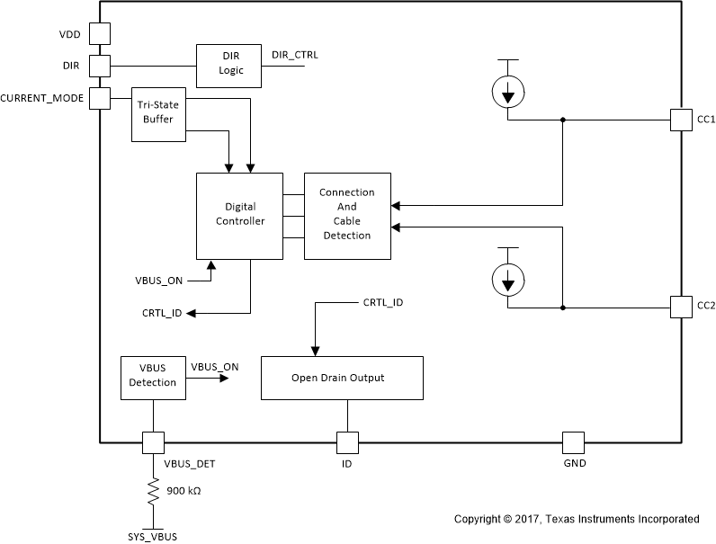
7.2 Functional Block Diagram

7.3 Feature Description
Table 1. Supported Features for the TUSB319-Q1 Device by Mode
| SUPPORTED FEATURES | DFP |
|---|---|
| Port attach and detach | Yes |
| Cable orientation | Yes |
| Current advertisement | Yes |
| Legacy cables | Yes |
7.3.1 Downstream Facing Port (DFP) - Source
The TUSB319-Q1 is a DFP device; it presents the appropriate Rp resistors on both CC pins, based on the state of the CURRENT_MODE pin to advertise the desired current level (USB-standard, 1.5 A and 3 A).
The TUSB319-Q1 can operate with older USB Type-C 1.0 devices except for a USB Type-C 1.0 DRP device. This limitation is a result of backwards compatibility problem between USB Type-C 1.1 DFP and a USB Type-C 1.0 DRP.
7.3.2 Type-C Current Mode
The TUSB319-Q1 device supports both advertising Type-C current by means of the CURRENT_MODE pin, which allows the CC controller to advertise 500 mA (for USB2.0) or 900 mA (for USB3.1) if CURRENT_MODE pin is left unconnected or pulled to GND. If a higher level of current is required, the CURRENT_MODE can be pulled up to VDD through a 500-kΩ resistor to advertise medium current at 1.5 A or pulled up to VDD through a 10-kΩ resistor to advertise high current at 3 A. Table 2 lists the Type-C current advertisements and detection.
Table 2. Type-C Current Advertisement and Detection
| TYPE-C CURRENT | CURRENT ADVERTISEMENT | |
|---|---|---|
| Default | 500 mA (USB2.0) 900 mA (USB3.1) |
CURRENT_MODE = L |
| Medium - 1.5 A | CURRENT_MODE = M | |
| High - 3 A | CURRENT_MODE = H | |
7.3.3 VBUS Detection
The TUSB319-Q1 device supports VBUS detection according to the Type-C Specification. The system VBUS voltage must be routed through a 900-kΩ resistor to the VBUS_DET pin on the TUSB319-Q1. When voltage on VBUS_DET pin is below the VBUS(THR) and Rd is detected on either CC1 or CC2, the TUSB319 assumes system VBUS is at vSafe0V (VBUS < 800 mV) and will assert ID low.
If VBUS_DET pin is left unconnected system needs to ensure that the VBUS level is below vSafe0V before VBUS is enabled.
7.3.4 Cable Orientation
The TUSB319-Q1 detects the cable orientation by monitoring the voltage on the CC pins. When a voltage level within the proper threshold is detected on CC1, the DIR pin is pulled low. When a voltage level within the proper threshold is detected on CC2, the DIR is pulled high. The DIR pin is an open drain output.
7.4 Device Functional Modes
The TUSB319-Q1 device has two functional modes. Table 3 lists these modes:
Table 3. USB Type-C States According to TUSB319-Q1 Functional Modes
| MODES | GENERAL BEHAVIOR | STATES(1) |
|---|---|---|
| Unattached | USB port unattached. | Unattached.SRC |
| AttachWait.SRC | ||
| Active | USB port attached. | Attached.SRC |
7.4.1 Unattached Mode
Unattached mode is the primary mode of operation for the TUSB319-Q1 device, because a USB port can be unattached for a lengthy period of time. In unattached mode, all IOs are operational. After the TUSB319-Q1 device is powered up, the part enters unattached mode until a successful attach has been determined.
7.4.2 Active Mode
Active mode is defined as the port being attached. When in active mode, the TUSB319-Q1 device communicates to the system that the USB port is attached. This happens through the ID pin. The TUSB319-Q1 device exits active mode when the cable is unplugged.