ZHCSJJ9A april 2019 – december 2020 UC1825B-SP
PRODUCTION DATA
- 1
- 1 特性
- 2 应用
- 3 说明
- 4 Revision History
- 5 Pin Configuration and Functions
- 6 Specifications
- 7 Detailed Description
- 8 Application and Implementation
- 9 Power Supply Recommendations
- 10Layout
- 11Device and Documentation Support
- 12Mechanical, Packaging, and Orderable Information
8.1 Application Information
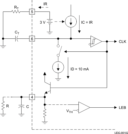
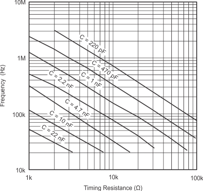
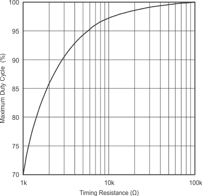
The oscillator of the UC1825B-SP is a saw tooth (see Figure 8-1). The rising edge is governed by a current controlled by the RT pin and value of capacitance at the CT pin (CCT). The falling edge of the sawtooth sets dead time for the outputs. Selection of RT must be done first, based on desired maximum duty cycle (see Figure 8-3). CT can then be chosen based on the desired frequency (RT) and DMAX (see Figure 8-2). Equation 1 shows the design equations.
Equation 1. 

Recommended values for RT range from 1 kΩ to 100 kΩ. Control of DMAX less than 70% is not recommended.
 Figure 8-1 Oscillator
