ZHCSDP1E January   2009  – February 2019 UC1842A-SP , UC1844A-SP

PRODUCTION DATA.  

  1. 特性
  2. 应用
  3. 说明
    1.     Device Images
      1.      简化原理图
  4. 修订历史记录
  5. Device Comparison Table
  6. Pin Configuration and Functions
    1.     Pin Functions
  7. Specifications
    1. 7.1 Absolute Maximum Ratings
    2. 7.2 ESD Ratings
    3. 7.3 Recommended Operating Conditions
    4. 7.4 Thermal Information
    5. 7.5 Electrical Characteristics
    6. 7.6 Electrical Characteristics (Radiation-Improved Devices)
    7. 7.7 Typical Characteristics
  8. Detailed Description
    1. 8.1 Overview
    2. 8.2 Functional Block Diagram
    3. 8.3 Feature Description
      1. 8.3.1 UVLO
      2. 8.3.2 Reference
      3. 8.3.3 Totem-Pole Output
    4. 8.4 Device Functional Modes
  9. Application and Implementation
    1. 9.1 Application Information
    2. 9.2 Typical Application
      1. 9.2.1 Design Requirements
      2. 9.2.2 Detailed Design Procedure
        1. 9.2.2.1 Oscillator
        2. 9.2.2.2 Current Sensing and Limiting
        3. 9.2.2.3 Error Amplifier
      3. 9.2.3 Application Curves
  10. 10Power Supply Recommendations
  11. 11Layout
    1. 11.1 Layout Guidelines
      1. 11.1.1 Feedback Traces
      2. 11.1.2 Input/Output Capacitors
      3. 11.1.3 Compensation Components
      4. 11.1.4 Traces and Ground Planes
    2. 11.2 Layout Example
  12. 12器件和文档支持
    1. 12.1 相关链接
    2. 12.2 接收文档更新通知
    3. 12.3 社区资源
    4. 12.4 商标
    5. 12.5 静电放电警告
    6. 12.6 术语表
  13. 13机械、封装和可订购信息

封装选项

机械数据 (封装 | 引脚)
散热焊盘机械数据 (封装 | 引脚)
订购信息

UVLO

The UVLO circuit ensures that VCC is adequate to make the UC184xA-SP fully operational before enabling the output stage. Figure 5 shows that the UVLO turnon and turnoff thresholds are fixed internally at 16 V and 10 V, respectively. The 6-V hysteresis prevents VCC oscillations during power sequencing.

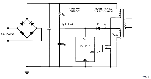
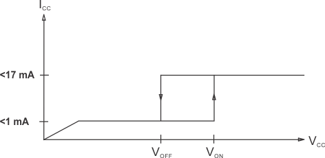
Figure 6 shows supply current requirements. Start-up current is < 1 mA for efficient bootstrapping from the rectified input of an off-line converter, as shown in Figure 7. During normal circuit operation, VCC is developed from auxiliary winding, WAux, with D1 and CIN. However, at start-up, CIN must be charged to 16 V through RIN. With a start-up current of 1 mA, RIN can be as large as 100 kΩ and still charge CIN when VAc = 90-V RMS (low line). Power dissipation in RIN would then be less than 350 mW even under high line (VAc = 130-V RMS) conditions.

During UVLO, the output driver is in a low state. While it does not exhibit the same saturation characteristics as normal operation, it can easily sink 1 mA, enough to ensure the MOSFET is held off.
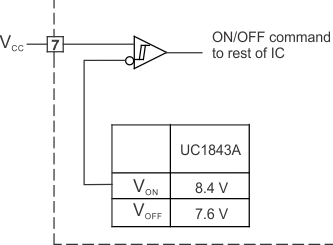
UC1842A-SP UC1844A-SP UVLO_lus872.gifFigure 5. UVLO Turnon TurnOff Threshold
UC1842A-SP UC1844A-SP UVLO_output_driver_LUSC14.gif
During UVLO, the output driver is biased to sink minor amounts of current.
Figure 6. Supply Current Requirements
UC1842A-SP UC1844A-SP providing_pwr_lus872.gifFigure 7. Providing Power to the UC184xA-SP