ZHCSL21B March   2020  – April 2022 UCC27284

PRODUCTION DATA  

  1. 特性
  2. 应用
  3. 说明
  4. Revision History B
  5. Pin Configuration and Functions
  6. Specifications
    1. 6.1 Absolute Maximum Ratings
    2. 6.2 ESD Ratings
    3. 6.3 Recommended Operating Conditions
    4. 6.4 Thermal Information
    5. 6.5 Electrical Characteristics
    6. 6.6 Switching Characteristics
    7. 6.7 Timing Diagrams
    8. 6.8 Typical Characteristics
  7. Detailed Description
    1. 7.1 Overview
    2. 7.2 Functional Block Diagram
    3. 7.3 Feature Description
      1. 7.3.1 Enable
      2. 7.3.2 Start-Up and UVLO
      3. 7.3.3 Input Stage
      4. 7.3.4 Level Shifter
      5. 7.3.5 Output Stage
      6. 7.3.6 Negative Voltage Transients
    4. 7.4 Device Functional Modes
  8. Application and Implementation
    1. 8.1 Application Information
    2. 8.2 Typical Application
      1. 8.2.1 Design Requirements
      2. 8.2.2 Detailed Design Procedure
        1. 8.2.2.1 Select Bootstrap and VDD Capacitor
        2. 8.2.2.2 Estimate Driver Power Losses
        3. 8.2.2.3 Selecting External Gate Resistor
        4. 8.2.2.4 Delays and Pulse Width
        5. 8.2.2.5 External Bootstrap Diode
        6. 8.2.2.6 VDD and Input Filter
        7. 8.2.2.7 Transient Protection
      3. 8.2.3 Application Curves
  9. Power Supply Recommendations
  10. 10Layout
    1. 10.1 Layout Guidelines
    2. 10.2 Layout Example
  11. 11Device and Documentation Support
    1. 11.1 第三方米6体育平台手机版_好二三四免责声明
    2. 11.2 Receiving Notification of Documentation Updates
    3. 11.3 支持资源
    4. 11.4 Trademarks
    5. 11.5 Electrostatic Discharge Caution
    6. 11.6 术语表
  12. 12Mechanical, Packaging, and Orderable Information

封装选项

机械数据 (封装 | 引脚)
散热焊盘机械数据 (封装 | 引脚)
订购信息

Application Curves

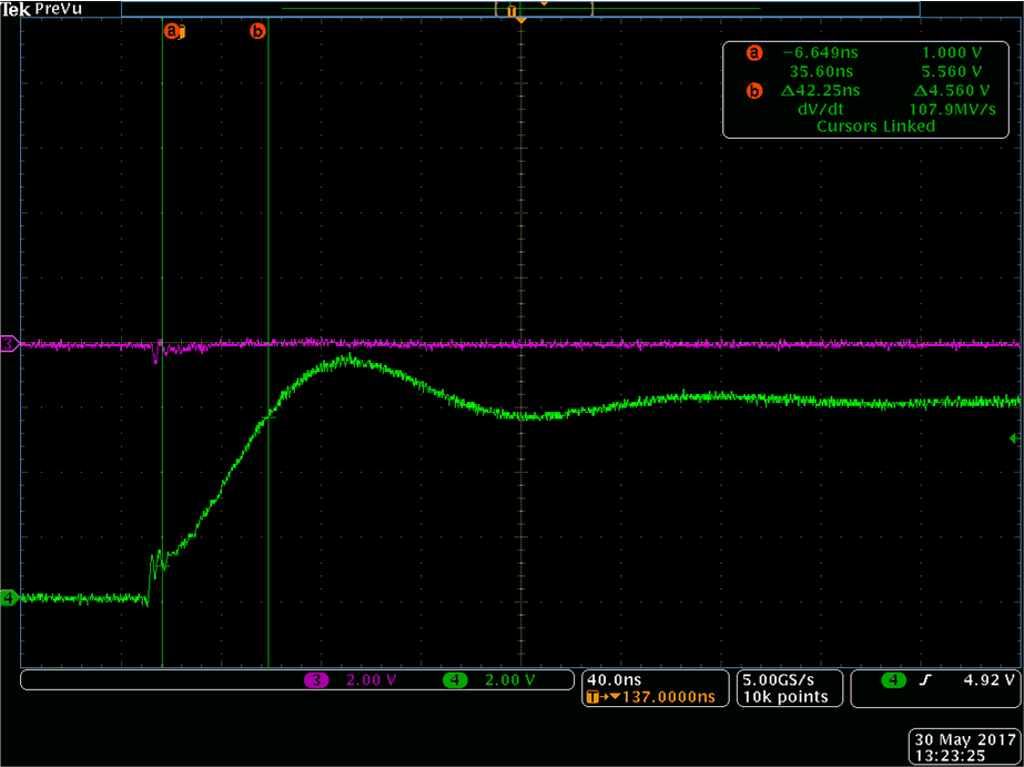
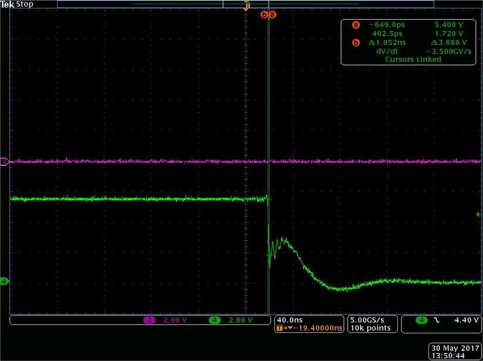
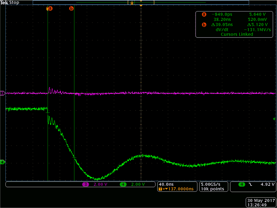
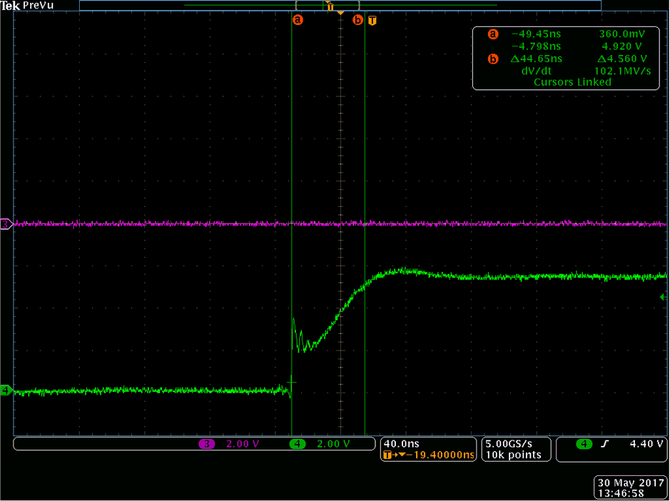
To minimize the switching losses in power supplies, turn-ON and turn-OFF of the power MOSFETs need to be as fast as possible. Higher the drive current capability of the driver, faster the switching. Therefore, the UCC27284 is designed with high drive current capability and low resistance of the output stages. One of the common way to test the drive capability of the gate driver device , is to test it under heavy load. Rise time and fall time of the outputs would provide idea of drive capability of the gate driver device. There must not be any resistance in this test circuit. Figure 8-3 and Figure 8-4 shows rise time and fall time of HO respectively of UCC27284. Figure 8-5 and Figure 8-6 shows rise time and fall time of LO respectively of UCC27284. For accuracy purpose, the VDD and HB pin of the gate driver device were connected together. HS and VSS pins are also connected together for this test.

Peak current capability can be estimated using the fastest dV/dt along the rise and fall curve of the plot. This method is also useful in comparing performance of two or more gate driver devices.

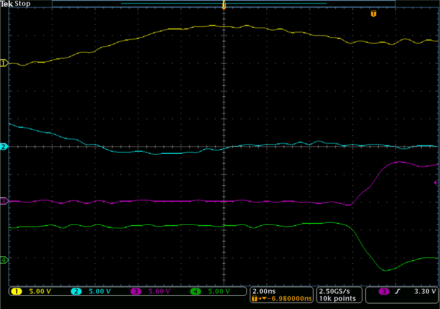
As explained in Section 8.2.2.4, propagation delay plays an important role in reliable operation of many applications.

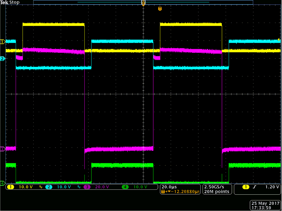
Figure 8-8 shows propagation delay and delay matching of UCC27284. Figure 8-9 shows input negative voltage handling capability of UCC27284.
GUID-D9072C4D-80E1-4C9C-BF56-A66BAFB8BDF9-low.gif
VDD = VHB = 6 V, HS = VSSCLOAD = 10 nFCh4 = HO
Figure 8-3 HO Rise Time
GUID-75B76F5B-E7F5-42CE-954F-896E98BDA41D-low.gif
VDD = VHB = 6 V, HS = VSSCLOAD = 10 nFCh4 = LO
Figure 8-5 LO Rise Time
GUID-39B59ED5-ED51-43D4-888A-C07AD9D1366F-low.gif
VDD = 6 VCLOAD = 2 nFCh1 = HI Ch2 = LI Ch3 = HO Ch4 = LO
Figure 8-7 Propagation Delay and Delay Matching
GUID-02A986E8-E396-4766-8569-6EFE96F7D301-low.gif
VDD = 10 V Vin = 100 VCL = 1 nFCh1 = HI Ch2 = LI Ch3 = HO Ch4 = LO
Figure 8-9 Input Negative Voltage
GUID-1FFA377A-7235-4021-8910-09667676E486-low.gif
VDD = VHB=6 V, HS = VSSCLOAD = 10 nFCh4 = HO
Figure 8-4 HO Fall Time
GUID-34E96DDA-3DD2-40A1-8C3C-2A134788E110-low.gif
VDD = VHB = 6 V, HS = VSSCLOAD = 10 nFCh4 = LO
Figure 8-6 LO Fall Time
GUID-1F108297-EB75-4634-9DD1-827D2E8FC422-low.gif
VDD = 6 VCLOAD = 2 nFCh1 = HI Ch2 = LI Ch3 = HO Ch4 = LO
Figure 8-8 Propagation Delay and Delay Matching