ZHCSN70F November 2002 – November 2023 UCC27423 , UCC27424 , UCC27425
PRODUCTION DATA
- 1
- 1 特性
- 2 应用
- 3 说明
- 4 Device Comparison Table
- 5 Pin Configuration and Functions
- 6 Specifications
- 7 Detailed Description
- 8 Application and Implementation
- 9 Power Supply Recommendations
- 10Layout
- 11Device and Documentation Support
- 12Revision History
- 13Mechanical, Packaging, and Orderable Information
封装选项
请参考 PDF 数据表获取器件具体的封装图。
机械数据 (封装 | 引脚)
- D|8
- P|8
- DGN|8
散热焊盘机械数据 (封装 | 引脚)
- DGN|8
订购信息
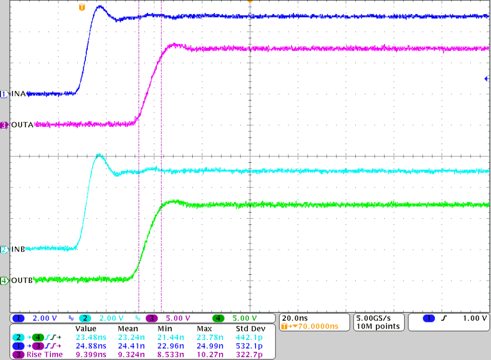
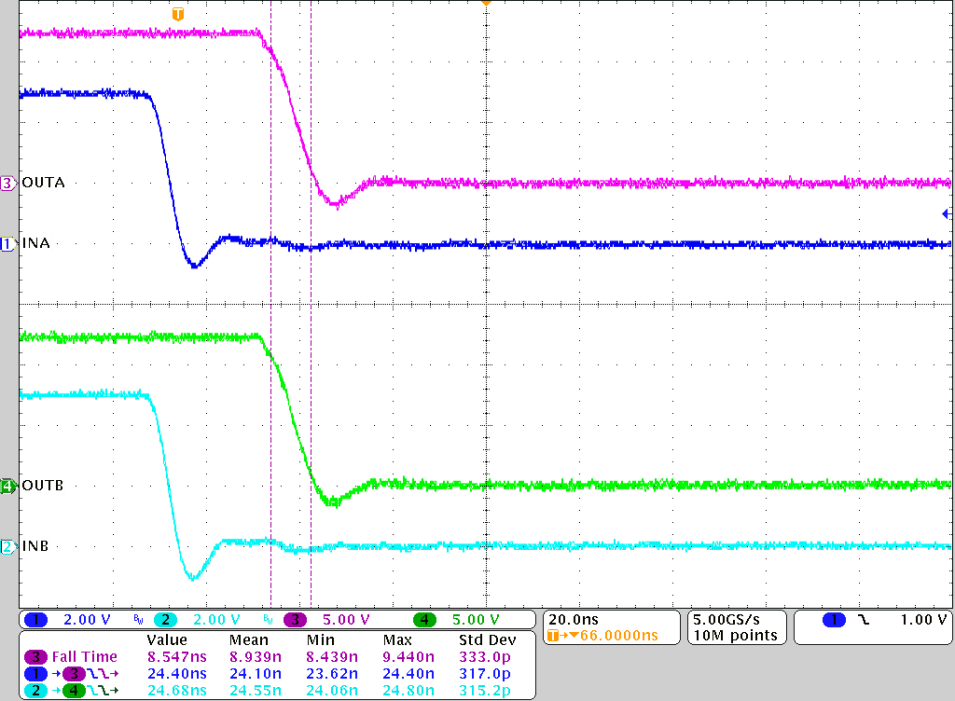
8.2.3 Application Curves
Figure 8-5 and Figure 8-6 shows rising/falling time and turn-on/off propagation delay testing waveform in room temperature for UCC27424, and waveform measurement data (see the bottom part of the waveform). Each channel, INA/INB/OUTA/OUTB, is labeled and displayed on the left hand of the waveforms.
The load capacitance testing condition is 1.8 nF, VDD = 12 V, and f = 300 kHz.
HI and LI share one same input from function generator, therefore, besides the propagation delay and rising/falling time, the difference of the propagation delay between HO and LO gives the propagation delay matching data.
Note the linear rise and fall edges of the switching waveforms. This is due to the constant output current characteristic of the driver as opposed to the resistive output impedance of traditional MOSFET-based gate drivers.

