SLUS168E Apr   1999  – August 2015 UCC2808-1 , UCC2808-2 , UCC3808-1 , UCC3808-2

PRODUCTION DATA.  

  1. Features
  2. Applications
  3. Description
  4. Revision History
  5. Pin Configuration and Functions
  6. Specifications
    1. 6.1 Absolute Maximum Ratings
    2. 6.2 ESD Ratings
    3. 6.3 Recommended Operating Conditions
    4. 6.4 Electrical Characteristics
    5. 6.5 Typical Characteristics
  7. Detailed Description
    1. 7.1 Overview
    2. 7.2 Functional Block Diagram
    3. 7.3 Feature Description
      1. 7.3.1 Pin Descriptions
    4. 7.4 Device Functional Modes
      1. 7.4.1 VCC
  8. Application and Implementation
    1. 8.1 Application Information
    2. 8.2 Typical Application
      1. 8.2.1 Design Requirements
      2. 8.2.2 Detailed Design Procedure
      3. 8.2.3 Application Curves
  9. Power Supply Recommendations
  10. 10Layout
    1. 10.1 Layout Guidelines
    2. 10.2 Layout Example
  11. 11Device and Documentation Support
    1. 11.1 Related Links
    2. 11.2 Documentation Support
      1. 11.2.1 Related Documentation
    3. 11.3 Community Resources
    4. 11.4 Trademarks
    5. 11.5 Electrostatic Discharge Caution
    6. 11.6 Glossary
  12. 12Mechanical, Packaging, and Orderable Information

封装选项

机械数据 (封装 | 引脚)
散热焊盘机械数据 (封装 | 引脚)
订购信息

10 Layout

10.1 Layout Guidelines

  1. Locate the VDD capacitor as close as possible between the VDD terminal and GND of the UCCx808-x, tracked directly to both terminals.
  2. A small, external filter capacitor is recommended on the CS terminal. Track the filter capacitor as directly as possible from the CS to GND terminal.
  3. The tracking and layout of the FB terminal and connecting components is critical to minimizing noise pick-up and interference in the magnetic sensing block. Reduce the total surface area of trances on the FB net to a minimum.
  4. The OUTA/OUTB terminal has high internal sink/source current capability. An external gate resistor is recommended. The value depends on the choice of power MOSFET, efficiency and EMI considerations. A pulldown resistor on the gate of the external MOSFET is recommended to prevent the MOSFET gate from floating on if there is an open-circuit error in the gate drive path.

10.2 Layout Example
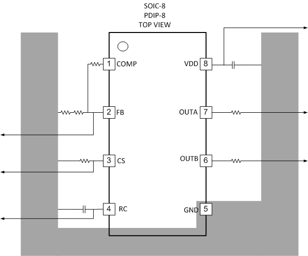
UCC2808-1 UCC2808-2 UCC3808-1 UCC3808-2 layout_sample.gifFigure 9. Layout Example