ZHCSKG7B June   2019  – February 2024 UCC5390-Q1

PRODUCTION DATA  

  1.   1
  2. 特性
  3. 应用
  4. 说明
  5. Pin Configuration and Function
  6. Specifications
    1. 5.1  Absolute Maximum Ratings
    2. 5.2  ESD Ratings
    3. 5.3  Recommended Operating Conditions
    4. 5.4  Thermal Information
    5. 5.5  Power Ratings
    6. 5.6  Insulation Specifications for DWV Package
    7. 5.7  Safety-Related Certifications For DWV Package
    8. 5.8  Safety Limiting Values
    9. 5.9  Electrical Characteristics
    10. 5.10 Switching Characteristics
    11. 5.11 Insulation Characteristics Curves
    12. 5.12 Typical Characteristics
  7. Parameter Measurement Information
    1. 6.1 Propagation Delay, Inverting, and Noninverting Configuration
      1. 6.1.1 CMTI Testing
  8. Detailed Description
    1. 7.1 Overview
    2. 7.2 Functional Block Diagram
    3. 7.3 Feature Description
      1. 7.3.1 Power Supply
      2. 7.3.2 Input Stage
      3. 7.3.3 Output Stage
      4. 7.3.4 Protection Features
        1. 7.3.4.1 Undervoltage Lockout (UVLO)
        2. 7.3.4.2 Active Pulldown
        3. 7.3.4.3 Short-Circuit Clamping
    4. 7.4 Device Functional Modes
      1. 7.4.1 ESD Structure
  9. Application and Implementation
    1. 8.1 Application Information
    2. 8.2 Typical Application
      1. 8.2.1 Design Requirements
      2. 8.2.2 Detailed Design Procedure
        1. 8.2.2.1 Designing IN+ and IN– Input Filter
        2. 8.2.2.2 Gate-Driver Output Resistor
        3. 8.2.2.3 Estimate Gate-Driver Power Loss
        4. 8.2.2.4 Estimating Junction Temperature
      3. 8.2.3 Selecting VCC1 and VCC2 Capacitors
        1. 8.2.3.1 Selecting a VCC1 Capacitor
        2. 8.2.3.2 Selecting a VCC2 Capacitor
        3. 8.2.3.3 Application Circuits With Output Stage Negative Bias
      4. 8.2.4 Application Curve
  10. Power Supply Recommendations
  11. 10Layout
    1. 10.1 Layout Guidelines
    2. 10.2 Layout Example
    3. 10.3 PCB Material
  12. 11Device and Documentation Support
    1. 11.1 Device Support
      1. 11.1.1 第三方米6体育平台手机版_好二三四免责声明
    2. 11.2 Documentation Support
      1. 11.2.1 Related Documentation
    3. 11.3 Certifications
    4. 11.4 接收文档更新通知
    5. 11.5 支持资源
    6. 11.6 Trademarks
    7. 11.7 静电放电警告
    8. 11.8 术语表
  13. 12Revision History
  14. 13Mechanical, Packaging, and Orderable Information

封装选项

机械数据 (封装 | 引脚)
散热焊盘机械数据 (封装 | 引脚)
订购信息

说明

UCC5390-Q1 是一款单通道隔离式栅极驱动器,具有 10A 最小峰值拉电流和 10A 最小峰值灌电流,专为驱动 MOSFET、IGBT 和 SiC MOSFET 而设计。UCC5390-Q1 的 UVLO2 以 GND2 为基准,有利于使用双极电源并优化 SiC 和 IGBT 开关行为和稳健性。

UCC5390-Q1 采用 8.5mm SOIC-8 (DWV) 封装,可支持高达 5kVRMS 的隔离电压。输入侧通过 SiO2 电容隔离技术与输出侧相隔离,隔离栅寿命超过 40 年。凭借高驱动强度和真正的 UVLO 检测,该器件非常适用于在车载充电器和牵引逆变器等应用中驱动 IGBT 和 SiC MOSFET。

与光耦合器相比,UCC5390-Q1 的器件间偏移更低,传播延迟更小,工作温度更高,并且 CMTI 更高。

器件信息
器件版本 封装(1) 封装尺寸(标称值)
UCC5390-Q1 DWV (SOIC-8) 7.5mm × 5.85mm
有关所有可选封装,请参阅节 13
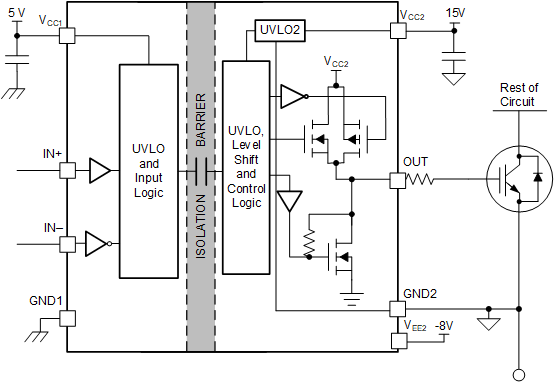
GUID-3EBBC118-ED30-4F10-B44D-A4BFD966B7C3-low.gif功能方框图