ZHCS429J March 2012 – November 2021 UCD3138
PRODUCTION DATA
- 1 特性
- 2 应用范围
- 3 说明
- 4 功能方框图
- 5 Revision History
- 6 Device Comparison Table
- 7 Pin Configuration and Functions
- 8 Specifications
-
9 Detailed Description
- 9.1 Overview
- 9.2 ARM Processor
- 9.3 Memory
- 9.4 System Module
- 9.5
Feature Description
- 9.5.1 Sync FET Ramp and IDE Calculation
- 9.5.2 Automatic Mode Switching
- 9.5.3 DPWMC, Edge Generation, IntraMux
- 9.5.4 Filter
- 9.5.5 Communication Ports
- 9.5.6 Miscellaneous Analog
- 9.5.7 Package ID Information
- 9.5.8 Brownout
- 9.5.9 Global I/O
- 9.5.10 Temperature Sensor Control
- 9.5.11 I/O Mux Control
- 9.5.12 Current Sharing Control
- 9.5.13 Temperature Reference
- 9.6 Device Functional Modes
-
10Application and Implementation
- 10.1 Application Information
- 10.2
Typical Application
- 10.2.1 Design Requirements
- 10.2.2 Detailed Design Procedure
- 10.2.3 Application Curves
- 11Power Supply Recommendations
- 12Layout
- 13Device and Documentation Support
- 14Mechanical Packaging and Orderable Information
封装选项
机械数据 (封装 | 引脚)
散热焊盘机械数据 (封装 | 引脚)
订购信息
9.5.5.2 PMBUS
The PMBus Interface supports independent master and slave modes controlled directly by firmware through a processor bus interface. Individual control and status registers enable firmware to send or receive I2C, SMBus or PMBus messages in any of the accepted protocols, in accordance with the I2C Specification, SMBus Specification (Version 2.0) and the PMBUS Power System Management Protocol Specification.
The PMBus interface is controlled through a processor bus interface, utilizing a 32-bit data bus and 6-bit address bus. The PMBus interface is connected to the expansion bus, which features 4 byte write enables, a peripheral select dedicated for the PMBus interface, separated 32-bit data buses for reading and writing of data and active-low write and output enable control signals. In addition, the PMBus Interface connects directly to the I2C/SMBus/PMBus Clock, Data, Alert, and Control signals.
Example: PMBus Address Decode via ADC12 Reading
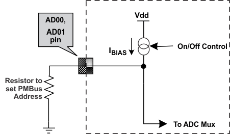
The user can allocate 2 pins of the 12-bit ADC input channels, AD_00 and AD_01, for PMBus address decoding. At power-up the device applies IBIAS to each address detect pin and the voltage on that pin is captured by the internal 12-bit ADC.
Where bin(VAD0x) is the address bin for one of 12 address as shown in Figure 9-13.
 Figure 9-13 PMBus Address Detection Method